The intricate world of industrial automation and mechanical design often presents subtle yet critical distinctions that, if misunderstood, can lead to significant operational inefficiencies, system failures, or, more critically, severe safety hazards. One such pervasive misconception revolves around the "self-locking" characteristic of certain gearmotors, particularly those incorporating worm gearing. While these gear types offer undeniable advantages for specific applications, their inherent locking behavior is frequently misconstrued as an active braking mechanism, a misapplication that design engineers must vigilantly avoid.
The Mechanics of Self-Locking: A Deeper Dive into Worm Gears
Fractional-horsepower gearmotors are fundamental components in a myriad of applications, from medical devices to consumer appliances and light industrial machinery. When selecting a gearmotor, OEM design engineers meticulously evaluate various parameters, including torque, speed, efficiency, and footprint. In certain scenarios, worm gearing is specified due to its compact nature, high reduction ratios, and its purported "self-locking" attribute. A worm gear assembly consists of a worm (a screw-like gear) and a worm wheel (a spur gear or helical gear meshing with the worm). The unique geometry of this pairing is what gives rise to its self-locking property.

The "self-locking" phenomenon in worm gears occurs when the friction between the worm and the worm wheel is sufficient to prevent the worm wheel from driving the worm. This irreversibility is a function of the worm’s lead angle and the coefficient of friction between the meshing surfaces. Specifically, if the lead angle of the worm is less than the angle of friction between the gear materials, the system will resist backdriving. In practical terms, this means that if power to the motor is removed, and an external load attempts to rotate the output shaft (the worm wheel), the friction in the gear mesh prevents this rotation, effectively holding the load in position.
However, this critical characteristic is often misinterpreted. The term "self-locking" accurately describes a static condition, where the gearmotor, once stopped, maintains its position against an applied load without continuous power. It is a passive holding function, not an active deceleration or stopping mechanism. This distinction is paramount in engineering safety and performance.
Static Hold vs. Dynamic Braking: A Crucial Engineering Divide
A common misconception among some engineers is that a self-locking gearbox will cause an axis to come to a rapid halt and firmly hold its position immediately upon power cut-off. This belief, while intuitively appealing, fundamentally misunderstands the physics at play. No gear assembly, including those with worm gears, is inherently capable of absolute, instantaneous self-locking from a state of motion. The locking behavior of worm gears manifests only from a static (stopped) state.

To clarify, "dynamic braking" refers to an electromechanical system’s active capacity to slow down or halt a moving axis. This involves dissipating the kinetic energy of the moving load. In contrast, the "self-locking" of a worm gear only engages once the system’s inertia has been overcome and it has reached a complete standstill. An axis driven by a worm gearmotor, even after electrical power is removed, will continue to turn due to its inherent inertia until that kinetic energy is dissipated through other means or until the system naturally decelerates to a stop, at which point the static self-locking mechanism can engage.
Consider the implications: if a heavy load is being lifted by a worm gearmotor, and power is suddenly lost, the load will not instantly freeze in place. Instead, it will continue to move, albeit decelerating, until its kinetic energy is spent. Only then will the worm gear’s static self-locking property prevent it from backdriving further. Relying solely on the self-locking feature for dynamic stopping can lead to uncontrolled motion, potential damage to machinery, and, most critically, severe injury to personnel.
Understanding Braking Mechanisms in Motion Control
To achieve true dynamic braking and ensure safety, dedicated braking systems are essential. These can take various forms, each with its own operational principles and applications:

- Friction Brakes: These are perhaps the most common type, utilizing friction pads or discs to create resistance against a rotating shaft. Electromagnetic friction brakes, for example, use an electromagnet to engage or disengage friction surfaces. They are widely used for holding loads, emergency stops, and controlled deceleration. Spring-applied brakes are a common failsafe mechanism, engaging automatically when power is removed and requiring electrical current to disengage.
- Dynamic Braking (Electrical): This method, distinct from the broader term used in this context, specifically refers to using an electric motor’s inherent properties to slow it down. This can involve shorting the motor windings (DC motors) or feeding power back into the grid (regenerative braking) or dissipating it through resistors (dynamic braking with resistors). While effective for slowing the motor itself, these methods primarily address motor inertia, not necessarily the entire mechanical system’s load inertia, and may not provide a sustained holding torque.
- Hydraulic/Pneumatic Brakes: These systems use fluid pressure to actuate braking mechanisms, often found in heavy industrial applications requiring high braking forces.
The key takeaway is that an active braking system is designed to dissipate energy and control motion, whereas a self-locking worm gear is designed to prevent motion once the system is already at rest.
Real-World Applications and the Imperative for Integrated Safety
The proper understanding and application of self-locking gearmotors, often in conjunction with dedicated braking systems, are critical across various industries.
-
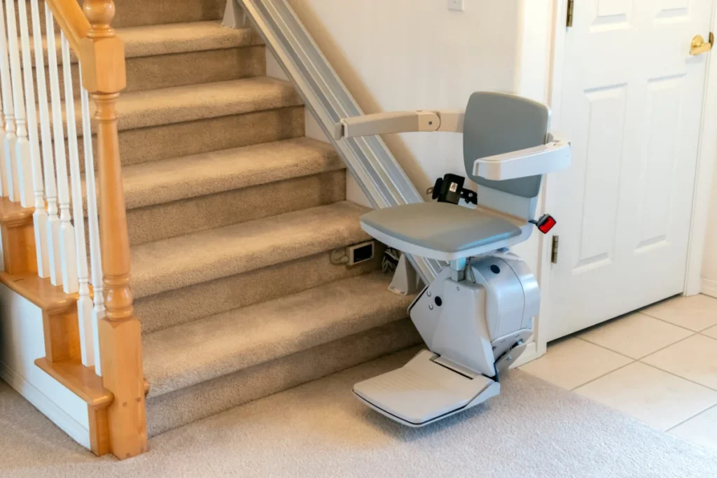
Stair Lifts and Mobility Applications: These systems are a prime example where both dynamic braking and static holding are indispensable. A stair lift, designed to transport individuals up and down stairs, demands absolute safety. When the lift needs to stop—either at the top/bottom or mid-travel—a dedicated brake is required to quickly and smoothly bring the assembly to a halt. This prevents overshooting and ensures passenger comfort and safety. Once stopped, especially in the event of a power failure, the self-locking gearbox becomes crucial. It holds the lift securely in place, preventing it from drifting downwards due to gravity, even without continuous power input. This dual-layer safety mechanism prioritizes efficiency by allowing the motor to be de-energized once stationary, relying on the worm gear for a sustained hold, while the brake ensures controlled stops.

-
Rotisserie Ovens: Commercial rotisserie ovens, found in supermarkets and restaurants, require precise control over the rotation of meat spits. Safety protocols dictate that the turning must pause when the oven door is opened to prevent burns from rotating hot items. Here, the challenge lies in potential weight imbalances; if two chickens are on one side of a spit and none on the other, gravity could cause the spit to continue rotating even after the motor is de-energized. A brake is essential to bring the rotisserie spits to a complete, immediate stop. Following this, the self-locking gearbox ensures that the spits remain immobile while the door is open, guaranteeing safety for operators. Without the brake, the inertia and gravitational imbalance could lead to uncontrolled rotation, posing a burn risk.
-
Industrial Conveyors and Lifting Equipment: In environments where loads are moved vertically or on inclines, the combination of a brake and a self-locking gearmotor is often the standard. Conveyors handling heavy items on an incline must be able to stop and hold the load safely at any point, preventing rollback. Cranes and hoists lifting substantial weights require robust braking systems for controlled descent and emergency stops, supplemented by the inherent static hold of worm gears to maintain position during extended pauses or power interruptions.
The Counter-Requirement: Backdrivability for Failsafe Operations
While many applications demand the static holding power of self-locking gears, an equally important set of applications necessitates the exact opposite: full backdrivability. Here, the system must offer minimal resistance to external forces, allowing for manual operation or a failsafe mechanism to take over in the event of power loss. Design engineers, though not explicitly requesting "backdrivable gearing," often specify requirements that implicitly demand it, such as "low resistance to backdriving."

-
Railroad Crossing Gates: These critical safety devices have stringent requirements for their operation. In the event of a power failure, the gates must fall down and block vehicle traffic. This is a failsafe design: a power failure means no other signal (like flashing lights) will alert drivers to an oncoming train, making the physical barrier paramount. This function relies on a gearbox that is easily backdrivable, allowing gravity acting on the gate arm’s weight to pull it into its closed, failsafe position. The design complexity is further compounded by the need for counterbalances on the arms, which reduce the motor size required to lift them, yet must still allow gravity to overpower the system when necessary. The low friction in a backdrivable gearbox is essential for this crucial safety function.
-
Parking Garage Barrier-Arm Gates: Similar to railroad gates, parking barriers often require backdrivability. If there’s a system failure, a power outage, or a user loses their ticket, an attendant or emergency personnel must be able to manually lift the gate. This necessitates an electromechanical assembly, including the motor’s gearbox, that can be easily backdriven by human force. Some designs incorporate electronics with manual override mechanisms, but a truly backdrivable gearbox provides a fundamental, mechanical failsafe, ensuring accessibility and preventing vehicles from being trapped.
Industry Standards and Best Practices
The critical distinction between self-locking and dynamic braking is not merely academic; it underpins numerous safety standards and regulatory guidelines in motion control. Organizations like OSHA (Occupational Safety and Health Administration) and various industry-specific bodies (e.g., for elevators, material handling, or machinery safety) mandate specific braking requirements for equipment to prevent uncontrolled movement, protect operators, and ensure public safety. These standards often dictate redundancy in braking systems, requiring independent mechanisms for normal operation, emergency stops, and power-off holding. Relying solely on the static self-locking of a worm gear without a supplementary, active brake in applications where dynamic stopping is needed would likely violate such standards and expose users to unacceptable risks.

The Role of Manufacturers and Education
Given the pervasive confusion surrounding "self-locking" gearmotor behavior, some manufacturers have taken proactive steps to de-emphasize the term or provide clearer educational resources. They aim to guide OEM engineers toward a more accurate understanding and proper application of these components. Companies like Bodine Electric Co., known for their expertise in fractional-horsepower gearmotors, frequently publish technical notes, host webinars, and engage in direct consultations to ensure their customers make informed design decisions. The insights shared by experts such as Terry Auchstetter of Bodine Electric Co. highlight the continuous need for clear communication and comprehensive engineering guidance.
In conclusion, while the self-locking characteristic of worm gearmotors offers genuine benefits in designs requiring static load holding without continuous power, it is imperative for design engineers to recognize its limitations. It is a passive holding mechanism, not an active braking system. For applications demanding controlled deceleration and dynamic stopping, a dedicated, appropriately sized brake is not merely an optional addition but a critical safety component. Integrating both a self-locking gearbox for static hold and an independent braking system for dynamic control represents best practice in motion control engineering, ensuring both operational efficiency and paramount safety across diverse industrial and commercial applications. The careful selection and integration of these components, guided by a thorough understanding of their fundamental principles, remain cornerstone elements of robust and reliable mechanical design.