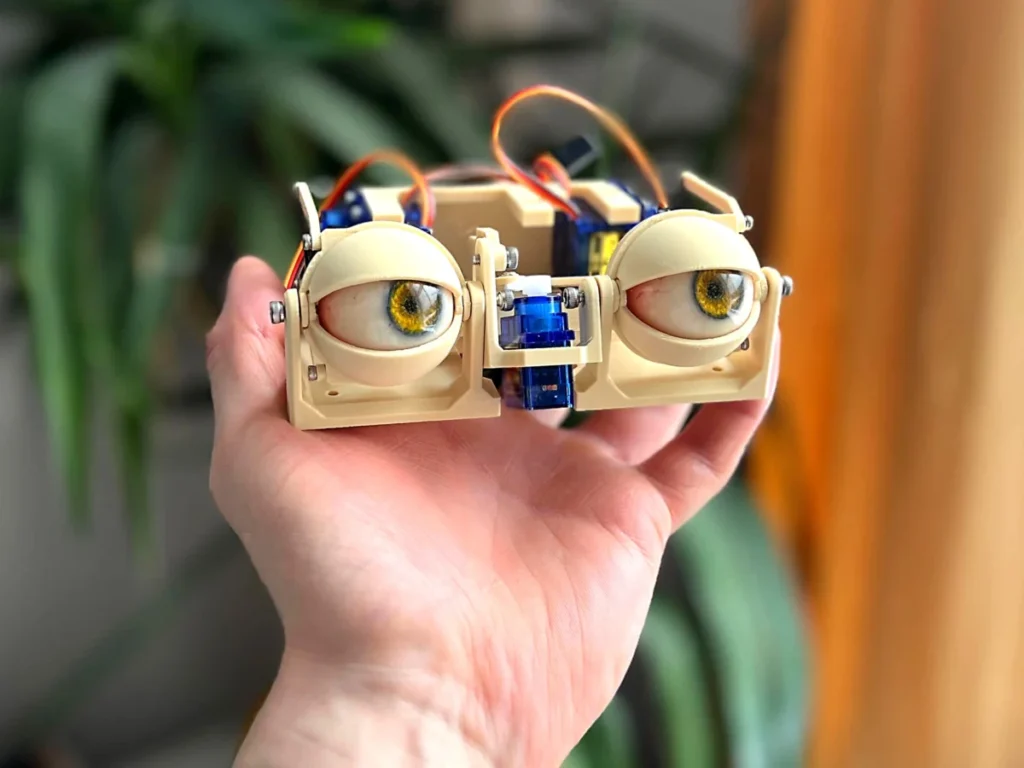
The intricate process of constructing sophisticated animatronic eye systems, designed to replicate lifelike gaze and eyelid movements, demands meticulous attention to mechanical detail and component integration. This technical guide outlines the critical assembly stages, from establishing foundational pivot points to integrating multiple servo actuators, providing insights into the engineering principles behind creating expressive artificial eyes.
Foundational Mechanics: Establishing the Y-Axis Pivot
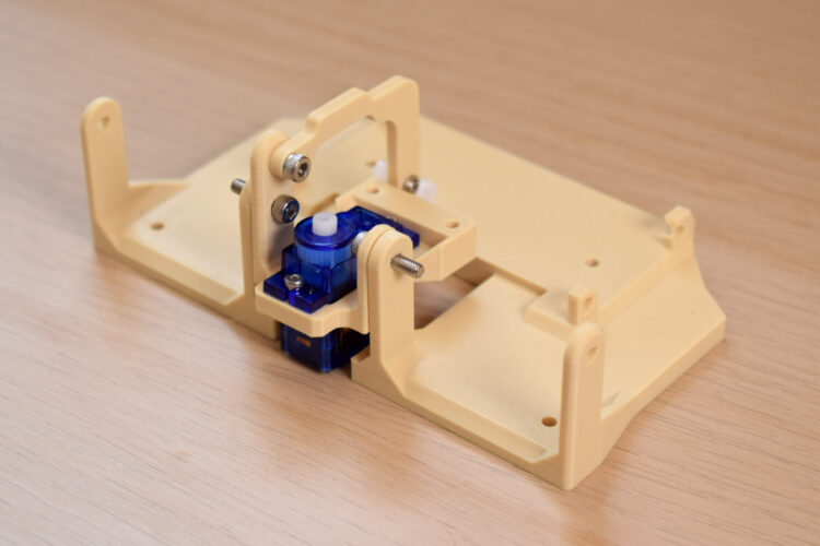
The initial phase of assembly focuses on establishing the primary pivot point, a critical element for the animatronic eye’s vertical (y-axis) motion and the synchronized movement of the eyelids. This pivotal connection is achieved by securely joining the two main structural bases using M3 bolts, typically specified at lengths of 10mm or 12mm. The choice of M3 bolts, a standard in precision small-scale robotics and electronics, ensures robust fastening while maintaining a compact footprint. The precise alignment of these bases is paramount, as any deviation can introduce friction or misalignment, compromising the smooth, fluid movement essential for realistic animation. This pivot serves as the central axis around which the entire eye assembly will articulate vertically, allowing for upward and downward glances, as well as providing the mechanical linkage for the nuanced opening and closing of the eyelids. The exact length of the bolt (10mm or 12mm) is often dictated by the thickness of the material used for the bases, typically 3D-printed polymer components, ensuring sufficient thread engagement without excessive protrusion.

Actuation for Horizontal Motion: Integrating the X-Axis Servo
Following the establishment of the y-axis pivot, the next crucial step involves integrating the primary actuator responsible for horizontal eye movement, or the x-axis. A micro servo, often a TowerPro SG90 as specified in later steps, is carefully positioned within its designated housing and secured using 4mm or 6mm M2 screws. The M2 screw size, smaller than the M3 bolts used for structural connections, is ideal for fastening delicate components like micro servos, which feature smaller mounting holes. This servo acts as the dedicated motor for panning the eyes left and right, forming the core of the system’s horizontal gaze control. The precise placement and firm attachment of this servo are critical to ensuring accurate and repeatable movements, preventing any slippage or play that could lead to jerky or unnatural eye motion. The specified screw lengths provide adequate depth for secure mounting without risking damage to the servo’s internal mechanisms.
Connecting the Y-Axis Arm and Servo Horn
With the primary axes defined and the x-axis servo in place, attention turns to connecting the y-axis arm to the sub-base. This connection is facilitated by a 4mm, 5mm, or 6mm M3 screw, depending on the specific design tolerances and material thickness. This arm is instrumental in translating the rotational motion of its dedicated servo into the vertical tilt of the eye assembly. Crucially, a servo horn, a small lever-like attachment that connects the servo shaft to the mechanical linkage, is then attached to the y-axis arm. The instruction specifies using the "third hole from the center" on the servo horn, which is a deliberate design choice. This particular hole provides an optimal balance between the range of motion and the mechanical advantage (torque) required to move the eye and eyelid assembly smoothly. A 4mm or 6mm M2 screw is used for this attachment, again emphasizing precision in securing smaller components. At this stage, it is imperative to visually inspect and confirm the correct orientation of all components. An incorrectly oriented arm or servo horn could result in inverted movements or mechanical binding, necessitating disassembly and re-calibration.
Building the X-Axis Assembly: Forks and Eye-Adaptors
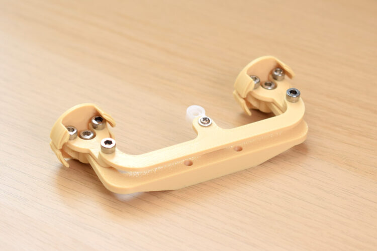
The construction of the x-axis assembly marks a significant step towards enabling horizontal eye movement. This assembly begins with screwing the "forks" into the "eye-adaptors" using 4mm, 5mm, or 6mm M3 bolts. The design intentionally features oversized holes in the forks, allowing the M3 screws to self-tap and create a strong, secure connection with the eye-adaptors. This method simplifies assembly and reduces the need for nuts in tight spaces. The eye-adaptors are custom components designed to cradle the artificial eye spheres, allowing them to pivot smoothly within the forks. The mention of "one goes in on a funny angle but you should be able to get it in" highlights a common challenge in intricate mechanical assemblies, where design constraints or manufacturing tolerances may necessitate minor manipulation during fitting. This step forms the framework that will hold the eyes and enable their lateral movement, driven by the x-axis servo.
Intricate Linkages: The Three-Point Connector and Eye Movement Coordination
Further refining the x-axis assembly, the three-point connector is attached to the top of the forks. This component, often 3D-printed, features an undersized hole designed to allow an M3 screw to bite firmly, ensuring a secure and stable connection. The three-point connector acts as a crucial linkage, coordinating the movement of the two individual eye adaptors. Simultaneously, a servo arm is attached to the final hole at the center of this three-point connector using a 5mm M3 bolt. It is common in such projects that the hole on the servo arm may require slight enlargement, typically drilled to 2.5mm–2.8mm, to perfectly accommodate the M3 screw. This modification ensures a snug fit and prevents play, which could translate into imprecise eye movements. Throughout this delicate process, regular manipulation of the assembly is strongly recommended. By physically moving the components, builders can identify and rectify any sources of friction or binding, guaranteeing a smooth and unimpeded range of motion once the system is fully operational. This iterative checking is vital for achieving the fluid, organic movements characteristic of believable animatronic eyes.
Integrating the Eye Center-Link and Eye Plugs
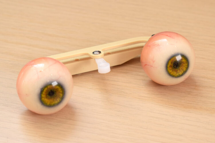
With the mechanical linkages progressing, the next step involves attaching the "eye center-link" to the eye adaptors. This connection is made with an 8mm M3 screw. The eye center-link is a critical component that bridges the two eye adaptors, ensuring their synchronized horizontal movement. Proper orientation is essential: the flat surface of the center-link must face upwards, while the sloping section faces downwards. This specific orientation is likely designed to accommodate the geometry of the eye spheres or to provide clearance for other moving parts. At this juncture, the artificial eye spheres themselves can be plugged into their respective adaptors. These eyes are typically lightweight, hollow spheres, often custom-made or repurposed, designed to sit snugly within the adaptors, ready to translate the mechanical movements into visual gaze changes. The secure attachment of the center-link and the insertion of the eyes bring the core ocular unit to life, marking a significant visual milestone in the assembly process.
Securing the Eye Assembly to the Sub-Base
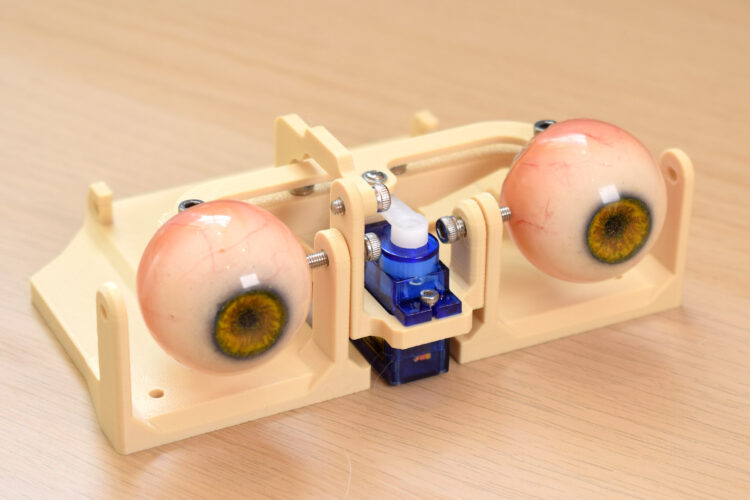
The completed eye assembly, comprising the eye adaptors, forks, three-point connector, and center-link, along with the integrated artificial eyes, is now ready to be securely mounted to the sub-base. This is achieved using two 12mm M3 bolts, strategically placed to distribute the load and ensure maximum stability. The sub-base acts as an intermediary structural layer, providing a stable platform for the complex eye mechanism while connecting it to the broader animatronic head or frame. The length of the 12mm M3 bolts indicates that they pass through multiple layers of material, providing a robust and enduring connection. This step ensures that the intricate eye movement mechanism is firmly anchored, preventing any unwanted vibrations or shifts that could detract from the realism of the animatronic character’s gaze. The entire assembly, now largely complete in its core functionality, represents a testament to precise mechanical design and careful execution.
The Servo Block: Powering Multiple Degrees of Freedom
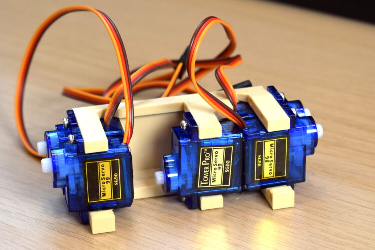
A critical element in achieving complex animatronic eye movements is the servo block, which houses multiple actuators. In this design, five TowerPro SG90 micro servos are loaded into the servo block. The TowerPro SG90 is a popular choice in the hobbyist and educational robotics communities due to its compact size, affordability, and adequate torque for light-duty applications like animatronic eyes. Each servo is positioned in a specific orientation, as indicated by accompanying photographic references, to ensure correct mechanical linkage and prevent interference. The block is then attached to the main base using four M3x10mm bolts. The presence of five servos implies a design capable of achieving multiple degrees of freedom (DOF): typically one for horizontal eye movement (x-axis pan), one for vertical eye movement (y-axis tilt), and two separate servos for independent upper eyelid control, with a fifth potentially for lower eyelid control or an additional expressive feature like eyebrow movement. This modular approach allows for complex, nuanced expressions that are far more convincing than simple two-axis movements. The secure mounting of the servo block is vital, as it is the central power hub for all eye and eyelid articulation.
Eyelid Control: Precision Linkages for Expressive Blinks
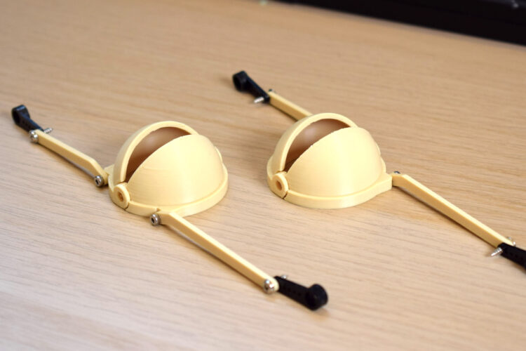
The final stages of assembly involve integrating the eyelids, which are crucial for conveying emotion and realism. The design specifies distinct upper and lower eyelids, each requiring precise control. Builders must carefully identify the correct eyelid components using visual aids. Each eyelid is then connected to its respective linkage using a 4mm or 6mm M2 screw. A servo arm is attached to the other end of this linkage, utilizing the last hole in the servo horn. Similar to previous steps, this smaller hole on the servo horn often requires careful drilling, typically to a diameter of 1.5mm–1.8mm, to perfectly accept the M2 screw without play. This attention to detail ensures that the eyelid movements are smooth, consistent, and free from mechanical slop. The precise leverage provided by using the outermost hole on the servo horn maximizes the eyelid’s range of motion, allowing for full blinks, half-blinks, and nuanced eye squints.
Final Eyelid Attachment and System Readiness
The concluding structural step involves attaching the fully assembled eyelids to the main base. At this stage, the eyelids are secured in place but are not yet connected to their respective servo horns. This intentional delay allows for a final check of the mechanical movement and ensures that the eyelids can articulate freely without obstruction. The lack of immediate servo horn connection implies that the final calibration and fine-tuning of the eyelid servos will occur once the entire mechanical assembly is complete and powered on, allowing for precise adjustment of their resting positions and full range of motion. This systematic approach, ensuring each component functions correctly before final integration and calibration, is a hallmark of robust engineering practices in animatronics. The completed mechanical structure now stands ready for electronic integration and programming, poised to bring lifelike expression to a static form.
Historical Context and Evolution of Animatronics
The development of animatronic eyes, as exemplified by this detailed assembly guide, is part of a rich history in the field of animatronics, which dates back over a century. Early pioneers like Walt Disney famously pushed the boundaries of mechanical animation, introducing characters like Abraham Lincoln at the 1964 New York World’s Fair, featuring groundbreaking facial expressions and synchronized movements. Over the decades, advancements in materials science, miniaturized electronics, and digital control systems have transformed animatronics from bulky, hydraulic-powered behemoths into compact, precise, and highly expressive mechanisms. The shift from pneumatic and hydraulic systems to electric servo motors, particularly micro servos like the TowerPro SG90, has democratized the field, making complex projects accessible to hobbyists and educational institutions. These modern systems allow for greater subtlety in movement, higher repeatability, and easier integration with microcontrollers, enabling dynamic and programmable performances.
Applications and Broader Implications
Animatronic eyes are not merely components in theme park attractions or film special effects; they represent a convergence of mechanical engineering, electronics, and artistic design with wide-ranging applications. In the entertainment industry, they are crucial for creating believable characters in movies, theatrical productions, and interactive museum exhibits. Beyond entertainment, animatronic eyes find utility in robotics, particularly in humanoid and social robots, where realistic eye contact and expressions enhance human-robot interaction and communication. In educational settings, projects like this serve as invaluable tools for teaching principles of kinematics, servo control, 3D printing, and integrated system design.
The modular design, emphasizing readily available components like M3 bolts and TowerPro SG90 servos, underscores the maker movement’s impact on advanced robotics. This approach lowers the barrier to entry for aspiring engineers and artists, fostering innovation and skill development within the global community. The use of 3D-printed custom parts further highlights the accessibility of rapid prototyping, allowing for bespoke designs tailored to specific aesthetic and functional requirements. The detailed instructions and visual aids provided in such guides are instrumental in empowering individuals to undertake complex projects, moving beyond basic electronics to create sophisticated electromechanical systems.
Analysis of Design Principles and Challenges
The design detailed in this assembly guide showcases several intelligent engineering principles. The separation of x and y-axis actuation, combined with dedicated eyelid servos, allows for independent control over different aspects of eye movement, resulting in more nuanced and realistic expressions. The use of servo horns with specific hole selections (e.g., "third hole from the center," "last hole") demonstrates an understanding of mechanical leverage, optimizing for either range of motion or torque depending on the specific linkage. The intentional oversizing of fork holes for self-tapping screws and the necessity for drilling servo arm holes highlight the practical realities of integrating commercially available components with custom-fabricated parts.
One of the ongoing challenges in animatronic eye design remains achieving truly organic motion. While discrete servo movements can be programmed, the fluid, almost imperceptible micro-movements of human eyes, along with the natural softness of eyelid blinks, require sophisticated programming algorithms and highly responsive hardware. Friction management, as implicitly stressed by the recommendation to "manipulate the assembly regularly," is paramount. Even slight friction can lead to jerky movements, increased servo strain, and reduced battery life. Miniaturization also presents challenges, balancing the need for compact components with sufficient mechanical strength and heat dissipation for multiple active servos.
Looking Ahead: The Future of Expressive Robotics
The continuous evolution of animatronic eye technology points towards a future where artificial characters and robots exhibit increasingly sophisticated emotional intelligence. Integration with advanced AI and machine learning could enable animatronic eyes to react dynamically to their environment, making natural eye contact, tracking subjects, and expressing emotions in real-time without pre-programmed scripts. Further advancements in material science could lead to even lighter, stronger, and more biologically accurate components, while micro-actuators with higher precision and silent operation would further enhance realism. Projects like the one detailed here serve as crucial stepping stones, contributing to a broader understanding of biomimetic design and pushing the boundaries of what is possible in the realm of expressive robotics and immersive entertainment.