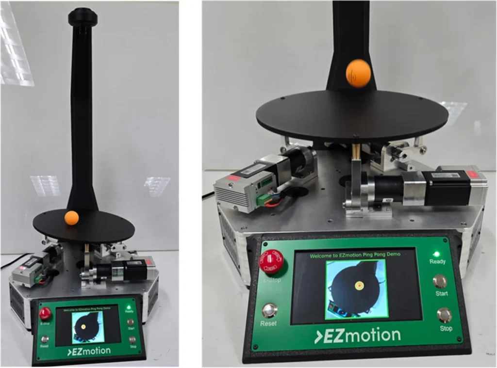
A cutting-edge demonstration platform, showcasing the robust capabilities of advanced servomotors, has been engineered to precisely manipulate the motion of a ping-pong ball in real-time. This sophisticated three-axis parallel kinematics system integrates synchronized servo actuation with visual feedback and instantaneous kinematic computation, pushing the boundaries of precision motion control. The initiative highlights the performance advantages of a specific line of servomotors, enabling dynamic balancing, swirling, and even bouncing of the inherently unpredictable lightweight object.
The Genesis of Precision: A Real-Time Control Challenge

The development of this parallel platform serves as a powerful testament to the efficacy of modern servomotor technology in demanding real-time applications. Conceived to exhibit the high-resolution motion, rapid response, and tight multi-axis synchronization offered by integrated servomotors, the system tackles several critical engineering challenges head-on. These include managing visual-feedback latency, ensuring seamless synchronization across multiple axes, and executing real-time inverse kinematics and Proportional-Integral-Derivative (PID) control on embedded hardware.
Charan Bhamra, a Mechatronics Engineer at Monolithic Power Systems, whose expertise likely contributed to this advanced project, underscores the practical implications of such precise control. The ability to coordinate multiple axes based on visual data and maintain tracking accuracy in real-time is not merely an academic exercise. It forms the bedrock for applications ranging from high-speed delta 3D printers and efficient pick-and-place machines to life-saving medical robotics and other industrial equipment where exacting motion control is paramount. The choice of a ping-pong ball as the controlled object is deliberate; its minimal mass and high susceptibility to air currents and minor disturbances present a formidable challenge, effectively amplifying any control inaccuracies and thus serving as an excellent benchmark for system responsiveness and stability.
Architectural Blueprint: Components and Connectivity

The intricate dance of real-time control is orchestrated through a meticulously designed system architecture. At its heart, the platform employs EZmotion MMS740100-24-C2-1 servomotors, each driving a limb of the parallel platform. These motors operate in CANopen Cyclic Synchronous Position (CSP) mode, a critical feature for achieving the tight coordination and jitter-free motion essential for the demonstration.
Visual input is captured by a camera positioned above the platform, recording the ball’s position at a moderate frame rate of 40 frames per second (fps). This raw visual data is then fed to a Raspberry Pi 5 device, a high-performance single-board computer, where it undergoes real-time processing via OpenCV computer vision libraries. The Raspberry Pi 5’s robust processing capabilities are crucial for quickly determining the ball’s actual location in the XY plane and its Z position.
Once processed, this critical positional information is transmitted to a Cortex M4 microcontroller unit (MCU) using the Serial Peripheral Interface (SPI) communication protocol. The MCU, acting as the system’s central nervous system, takes on the role of the motors’ initiator controller. It is responsible for the platform’s core control loop and the complex kinematic model.

The Brains of the Operation: Control Algorithms and Kinematics
The core control logic within the MCU is built around a sophisticated PID-based algorithm. This algorithm continuously evaluates the positional error of the ping-pong ball and translates it into a precise platform tilt angle and Z-translation adjustment. The PID controller’s parameters are finely tuned to ensure rapid error correction without overshooting, maintaining stability and responsiveness.
Crucially, the kinematic model then translates these desired platform tilt-angle and Z-translation instructions into specific position targets for each of the three servomotors. This inverse kinematics computation is performed in real-time by the MCU, calculating the exact crank angle required for each motor to achieve the desired platform orientation. The motors subsequently enter CSP mode via CANopen, receiving these precise position setpoints. This ensures a synchronized and deterministic motion across all three axes, allowing the platform to stabilize and control the ball even with fast-changing inputs.

Visual Tracking: The Eyes of the System
The division of computational labor between the MCU and the Raspberry Pi 5 is a cornerstone of the platform’s efficiency. While the MCU is dedicated to inverse kinematics and PID control, the Raspberry Pi 5 handles the computationally intensive visual feedback. It runs a lightweight Python script leveraging OpenCV to process video frames from the top-mounted USB camera at 40 fps.
The image processing pipeline involves several steps:

- Gaussian Blur: Applied to video frames to reduce noise and smooth the image, enhancing the accuracy of subsequent detection steps.
- HSV Conversion: Frames are converted from RGB to Hue, Saturation, and Value (HSV) color space. HSV is often preferred for color-based object tracking because it separates color information (Hue) from intensity (Value), making it less susceptible to lighting variations.
- Color Masking: To facilitate reliable tracking, the ping-pong ball is specifically colored orange. An orange color mask is applied in the HSV space, isolating the ball from the background.
- Contour Filtering: This step helps identify the boundaries of the masked ball. OpenCV’s contour detection algorithms are used to find continuous curves of points along the ball’s perimeter.
- Center Coordinate Extraction: The center coordinates (X and Y) of the ball are extracted from the smallest circle that completely encloses the largest detected contours. These coordinates provide the ball’s real-time position in the XY plane.
- Z-Position Determination: The ball’s height (Z position) is ingeniously determined by its apparent diameter in the camera’s view. As the ping-pong ball moves closer to the camera, its detected diameter in pixel units increases proportionally. This pixel-based diameter is then translated into a real-world Z-position in millimeters, providing crucial vertical feedback.
The Raspberry Pi 5 also includes an HDMI output for live rendering of the camera feed, displaying the post-processed ball tracking frames to a local screen, offering immediate visual confirmation of the system’s performance. The precise position and height data of the ball are then sent to the MCU via SPI for control loop calculations.
Kinematic Model Calculations: The Mathematical Foundation
The precise control of the parallel platform hinges on a series of inverse kinematic calculations. These computations determine the required motor crank angles to achieve a target platform tilt angle and Z-translation. The process begins with defining the global positions of the fixed-base joints and the local positions of the moving platform joints, which are distributed on a circle of a specific radius.

Rotation matrices play a fundamental role in defining the platform’s movement in three-dimensional space. Separate matrices account for rotation around the X-axis (θx), Y-axis (θy), and Z-axis (θz). These individual rotations are then combined into a single rotation matrix (R), which describes the overall rotation of the platform’s axes relative to the base’s axes.
Subsequently, the actual positions of each platform joint in global coordinates are calculated by applying the combined rotation matrix and the desired translation. Once these global joint positions are known, the necessary length of each limb of the parallel manipulator can be determined. This length is the straight-line distance between the fixed-base joint and its corresponding transformed platform joint. Finally, based on the required length of each limb and the known lengths of the crank arm and the connecting rod, the motor crank angle for each servomotor is computed. These complex 3D and 2D views illustrate how these equations precisely define the platform’s orientation and dictate the necessary crank angles for the motors.
Dynamic Modes: A Real-Time Ballet of Control

The platform demonstrates its versatility through a series of operational modes, each showcasing different aspects of its real-time control capabilities:
- Balancing: In this fundamental mode, the target ball location is fixed at the precise center of the platform. The PID controller continuously works to minimize any positional error by dynamically adjusting the platform’s tilt angles (θx and θy). This mode exemplifies the system’s ability to maintain a static equilibrium against disturbances.
- Circular Swirling: For this dynamic mode, the system follows a predefined two-dimensional array of time-varying reference points, forming a perfect circle with a 100mm radius in the XY plane. The PID controller ensures the ball accurately traces this circular trajectory, demonstrating coordinated multi-axis movement.
- Bouncing: This is arguably the most complex mode, requiring precise vertical control. The target height is set in millimeters, with the target location remaining at the platform’s center. To initiate bouncing, the system enters an "oscillation phase," where the platform executes rapid vertical movements to impart sufficient energy to lift the ball off its surface. This phase gradually increases the ball’s mechanical energy. Once a predefined energy threshold is met (indicating consistent bouncing), the controller transitions to a "bouncing mode." In this phase, the system applies minimal, synchronized vertical motion to sustain the bounce at the target height, focusing on optimal energy efficiency rather than driving the ball higher. The ball’s total energy (kinetic and potential) and velocity are estimated by tracking changes in its height over time.
Integrated Servomotors: The Powerhouse of the Platform
The core of this demonstration’s success lies in the integrated servomotors. The EZmotion MMS740100-24-C2-1, a 40-mm smart motor, embodies a paradigm shift in motor design. It features a permanent-magnet synchronous motor seamlessly integrated with a high-efficiency servo driver module and an embedded motion controller. This controller runs a nested control loop, meticulously regulating current, velocity, and position in real-time.

Further enhancing its capabilities, the motor includes an onboard CAN transceiver for direct integration into a CANopen network and a dedicated power management solution for stable internal voltages. By consolidating critical components—sensor, driver, controller, communication interface, and power—into a single, compact device, these servomotors eliminate the need for external boards and controllers. This integration dramatically simplifies wiring, reduces system complexity, and offers a true "plug-and-play" solution, accelerating development cycles and enhancing reliability. The MMS740100-24-C2-1 also boasts a 14-bit resolution magnetic position sensor, ensuring sub-degree accuracy in shaft position tracking.
CANopen Cyclic Synchronous Position (CSP) Mode: The Key to Synchronization
Synchronized motion is a hallmark of high-performance automation, and the CANopen protocol, specifically its Cyclic Synchronous Position (CSP) mode, is instrumental here. While other CANopen modes like Cyclic Synchronous Velocity (CSV) and Cyclic Synchronous Torque (CST) cater to velocity- and torque-driven applications, CSP mode is specifically designed for deterministic, position-based multi-axis control.

In CSP mode, the MCU, acting as the initiator, transmits precise position setpoints to each motor at a fixed and deterministic update rate. To ensure smooth and continuous motion between these discrete updates, each motor internally performs linear interpolation between consecutive setpoints. The motor controllers do not generate their own complex trajectories; instead, they rely on the initiator to continuously feed updated position targets.
From a communication standpoint, CSP mode utilizes Process Data Object (PDO) messages containing absolute target positions. These PDOs can be mapped, configured, and stored in the motor’s non-volatile memory. This robust communication ensures that the motor shaft follows a seamless trajectory, even though position targets are sampled at discrete intervals. The calculated crank angle values from the inverse kinematics are converted into these CSP position targets and broadcast synchronously across the CAN bus, maintaining highly coordinated and jitter-free motion across all three limbs of the platform.
Operational Sequence: From Homing to Dynamic Play

The operational sequence of the parallel platform is a carefully choreographed series of steps, ensuring precision and user-friendliness. The system commences with a torque-based homing routine for each servomotor. During this process, all three limbs retract inward at a controlled speed until they reach their mechanical hard stops, establishing a repeatable and accurate zero position.
Upon successful completion of the homing sequence, the platform automatically ascends to a predefined mid-height along the Z-axis. A green status LED illuminates, signaling successful initialization and indicating that the system is ready for operation and a user can safely place a ping-pong ball on the platform.
The manipulator then enters its active sequence, starting with the balancing mode. After a set period, it transitions to a circular swirl mode for 30 seconds, followed by the challenging bouncing mode for another 30 seconds. This sequence continuously loops as long as the system remains active, offering a comprehensive demonstration of its capabilities. Throughout the entire demonstration, a 7-inch display provides live visual feedback of the ball’s motion, allowing observers to appreciate the real-time control in action.

Beyond the Ping-Pong Ball: Real-World Implications
The technological principles demonstrated by this parallel-kinematics platform extend far beyond a mere ping-pong ball. The demand for such precision motion control is rapidly growing across numerous industries.
In medical robotics, similar architectures are being deployed to stabilize delicate endoscopic instruments, guide surgical tools with sub-millimeter accuracy, and assist in minimally invasive procedures where fine resolution and jitter-free motion are absolutely essential for patient safety and surgical efficacy. The ability to precisely control instruments in complex anatomical environments can revolutionize surgical outcomes.

Within industrial automation, integrated servomotors like those used in this demonstration are critical for imparting motion to optical alignment stages, high-speed pick-and-place heads, and micro-assembly manipulators. These applications demand unparalleled accuracy and repeatability to ensure product quality and production efficiency. The rise of delta 3D printers and advanced delta pick-and-place machines also leverages servo-driven parallel kinematic structures, benefiting from their high speed, precision, and large working envelopes relative to their footprint. These integrated solutions simplify machine design, reduce component count, and improve overall system reliability, contributing to the broader trend of smarter, more autonomous manufacturing processes.
The demonstration stands as a compelling illustration of how integrated servomotor technology, coupled with advanced real-time control algorithms and sophisticated vision systems, is poised to drive the next generation of precision automation across diverse sectors, making once-complex tasks seamlessly achievable. The ease of integration and high performance of systems like the EZmotion MMS740100-24-C2-1 signal a future where complex motion control is more accessible and robust than ever before.