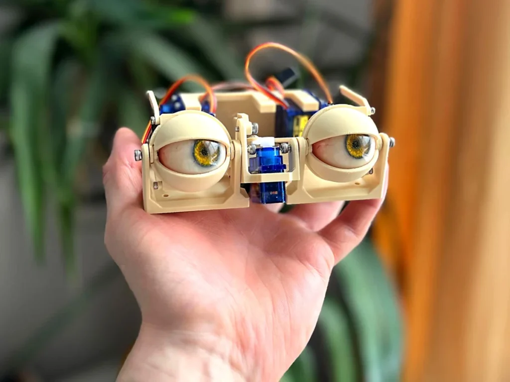
The meticulous assembly of advanced animatronic eyes represents a significant stride in accessible robotics, offering a detailed blueprint for creators aiming to imbue their projects with lifelike visual capabilities. This intricate process, centered on achieving both horizontal and vertical gaze, alongside realistic eyelid articulation, highlights the convergence of mechanical engineering and creative design within the burgeoning field of DIY animatronics. The construction methodology emphasizes precision component integration, utilizing standard hardware and micro-servos to replicate the complex kinematics of human ocular motion.
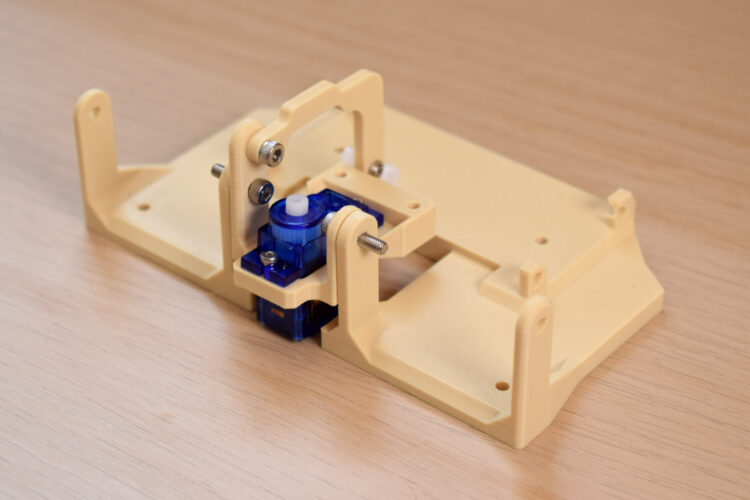
The foundation of the animatronic eye mechanism begins with establishing the primary pivot points essential for dynamic movement. Two critical base components are securely connected using either 10mm or 12mm M3 bolts. These metric bolts, commonly employed in robotics and precision engineering for their standardized sizing and robust fastening capabilities, ensure a stable structural connection. This particular pivot point is strategically designed to govern the y-axis motion of the eye—allowing for vertical gaze adjustments—and concurrently facilitate the synchronized movement of the eyelids. The choice of M3 bolts underscores a commitment to durability and ease of assembly, as M3 hardware is widely available and provides sufficient clamping force for small-scale robotic applications without over-stressing delicate components. The precise length (10mm or 12mm) is crucial to ensure optimal engagement with the threaded inserts or through-holes, preventing loosening while allowing for smooth rotational freedom at the pivot.

Following the establishment of the y-axis pivot, the next crucial step involves integrating the primary actuator for horizontal eye movement. A compact servo motor is positioned and fastened into place using 4mm or 6mm M2 screws. The M2 screw size, smaller than M3, is ideal for securing micro-servos like the TowerPro SG90, which often feature mounting tabs with pre-drilled holes designed for such dimensions. This servo acts as the dedicated actuator for the x-axis motion, controlling the left-to-right gaze of the animatronic eyes. The precise placement and secure fastening of this servo are paramount; any misalignment or instability could introduce backlash or jerky movements, compromising the realism of the eye’s motion. The servo’s compact size and relatively high torque-to-weight ratio make it an excellent choice for this application, allowing for agile and responsive horizontal positioning. Photography by Will Cogley illustrates this critical integration, providing visual clarity for builders to ensure correct orientation and secure attachment.
The subsequent phase focuses on linking the y-axis arm to the sub-base, a vital step for translating servo motion into vertical eye and eyelid movement. This connection is achieved with a 4mm, 5mm, or 6mm M3 screw, selected based on the specific thickness of the components to ensure a flush and secure fit without impeding movement. A servo horn, a common accessory for connecting mechanical linkages to servo shafts, is then attached to the y-axis arm. Specifically, it is fastened to the third hole from its center using a 4mm or 6mm M2 screw. This particular hole selection on the servo horn is not arbitrary; it dictates the leverage and angular displacement transferred from the servo to the y-axis arm, directly influencing the range and sensitivity of the vertical eye and eyelid motion. Builders are advised to meticulously verify the orientation of all components at this stage, as incorrect alignment can lead to restricted movement, binding, or even damage to the servo or mechanical linkages.
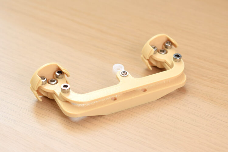
The construction then transitions to the intricate x-axis assembly, which is responsible for the synchronized horizontal movement of both eyes. This begins with screwing two "forks" into the eye-adaptors using 4mm, 5mm, or 6mm M3 bolts. The design incorporates oversized holes in the forks, a deliberate engineering choice to allow the M3 screws to "bite" directly into the material of the eye-adaptors. This self-tapping-like action creates a very secure, friction-fit connection, reducing the likelihood of loosening under repeated motion. The mention of one screw needing to go in at "a funny angle" suggests a tight or specific geometric constraint in the design, highlighting the fine tolerances often encountered in compact animatronic mechanisms. Despite the challenge, builders are reassured that the connection is achievable, underscoring the robust yet adaptable nature of the design. These forks and adaptors are typically fabricated from durable, lightweight materials such as 3D-printed ABS or PLA, or precision-cut acrylic, chosen for their balance of strength and ease of manufacturing in a DIY context.
Furthering the x-axis assembly, a "three-point connector" is affixed to the top of the forks. Here, an M3 screw is designed to bite into an undersized hole within the fork component, once again leveraging a tight thread engagement for a secure connection. Concurrently, a servo arm is attached to the final hole at the center of this three-point connector using a 5mm M3 bolt. A critical modification may be necessary at this juncture: the hole on the servo arm might require drilling out to 2.5mm–2.8mm to properly accommodate the M3 screw. This common adjustment in DIY robotics compensates for slight variations in component manufacturing or design, ensuring optimal fit. Throughout this intricate assembly, regular manipulation of the structure is strongly recommended to identify and mitigate any sources of friction. Smooth, unhindered movement is paramount for achieving fluid and natural animatronic eye motion, and early detection of friction points allows for timely adjustments or refinements.
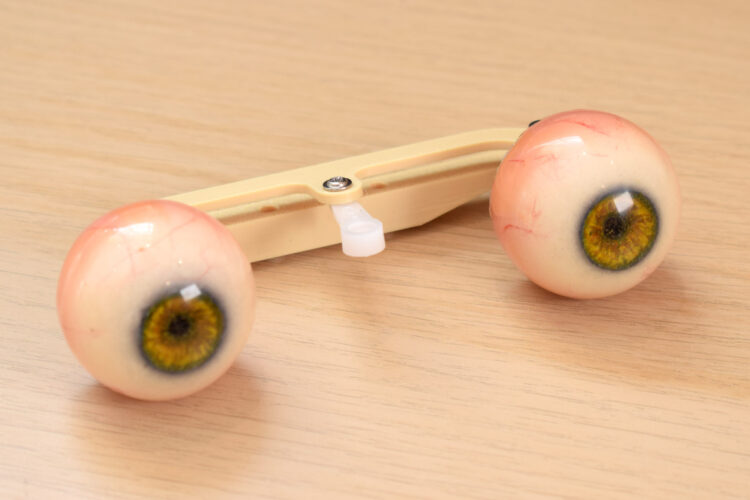
The eye center-link, a component crucial for maintaining the precise inter-ocular distance and synchronized movement, is then attached to the eye adaptors using an 8mm M3 screw. Attention to detail is emphasized here, with specific instructions to ensure the flat surface of the center-link faces upwards and the sloping section faces downwards. This orientation is critical for proper mechanical function and aesthetic integration. At this stage, the actual animatronic eyes—often custom-made spheres or commercially available doll eyes—can be plugged into their respective adaptors. The inclusion of the eyes early in the assembly process allows builders to visually confirm the mechanical alignment and begin to anticipate the final appearance and range of motion.
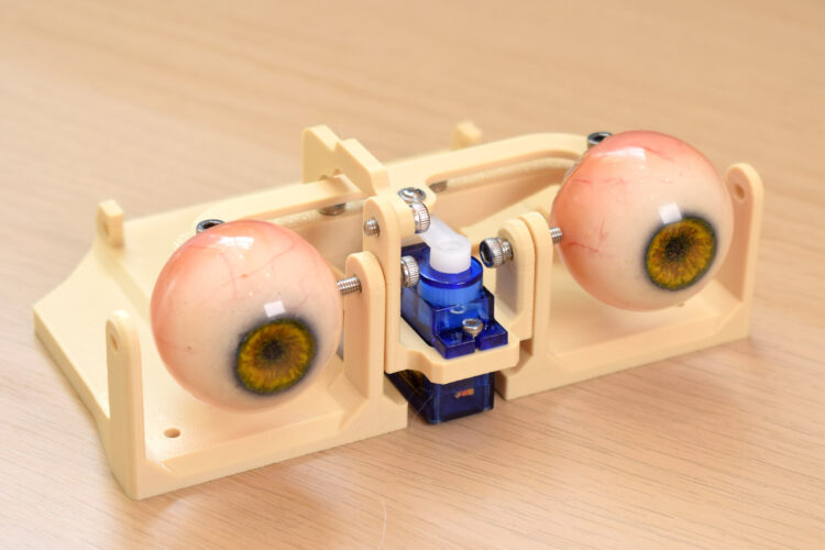
All these interconnected components—the x-axis assembly, eye center-link, and eye adaptors with eyes—are then securely fastened to the center of the sub-base using two 12mm M3 bolts. This central mounting point provides the primary structural support for the entire eye mechanism, anchoring it firmly to the overall animatronic head or housing. The robust M3 bolts ensure that the delicate eye assembly remains stable even during rapid or continuous movements, preventing wobble or displacement that could detract from the realism of the animation.
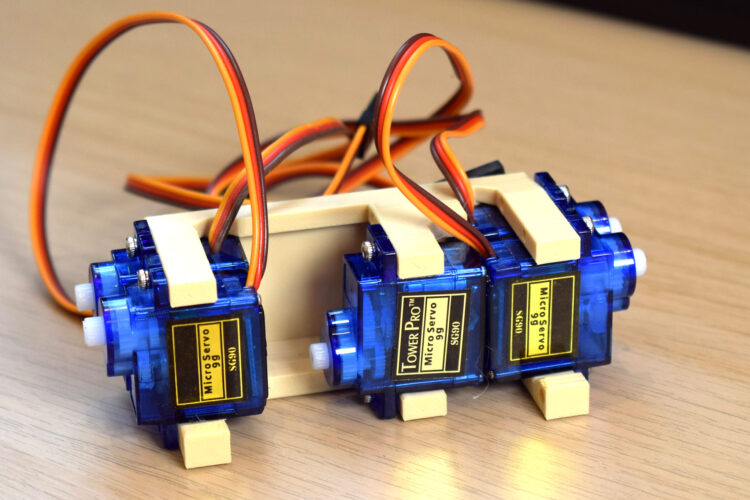
The next significant step involves preparing the servo block, the heart of the animatronic system’s motion control. This block is loaded with five TowerPro SG90 servos, carefully oriented as per the provided visual guide. The TowerPro SG90 is a ubiquitous micro servo in the hobby robotics and maker community, renowned for its affordability, compact size (typically 23×12.2x29mm), and sufficient torque (around 1.8 kg/cm at 4.8V) for light to medium load applications. Its 180-degree operational range and relatively quick response time make it ideal for animating eye movements and eyelid blinks. The use of five such servos implies a sophisticated control scheme, likely dedicating individual servos to specific movements: one for x-axis, one for y-axis, and potentially one for each upper and lower eyelid, with an additional servo for a broader head tilt or secondary facial expression. The servo block, once populated, is then attached to the main base using four M3x10mm bolts, ensuring a robust and stable platform for the entire array of actuators.
The final stages of assembly focus on the nuanced mechanics of the eyelids. Builders are instructed to carefully identify which eyelid corresponds to which mechanism, often aided by reference photographs. The relevant connector for each eyelid is then attached using a 4mm or 6mm M2 screw. A servo arm is subsequently connected to the other end of this linkage, specifically utilizing the last hole on the servo horn. Similar to previous steps, this hole might require drilling to a smaller diameter, typically 1.5mm–1.8mm, to perfectly accept the M2 screw, highlighting the need for iterative adjustments in precision builds. The specific hole on the servo horn is chosen to provide the correct leverage and range of motion for the eyelids, allowing for natural blinks and subtle expressive movements.
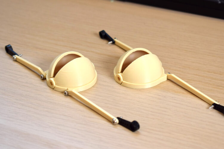
Finally, the completed eyelid assemblies are attached to the base structure. At this point, the servo horns are not yet connected to the servos themselves, which is a common practice in animatronics and robotics assembly. This allows for the mechanical components to be installed and verified for free movement before the servos are electronically calibrated and linked. This staged approach helps prevent potential damage to the servos during initial mechanical alignment and allows for easier adjustment of the servo’s neutral position once powered. The careful integration of these eyelid mechanisms is crucial for achieving truly expressive animatronic eyes, moving beyond simple gaze direction to convey emotion and realism through blinking and subtle eye squints.
Innovation in DIY Robotics: Background and Context
The development of accessible animatronic eye assembly guides, such as this one featured by Makezine, underscores a broader trend in robotics: the democratization of complex technologies. Animatronics, historically the domain of large film studios and theme park attractions, is increasingly becoming approachable for independent makers, educators, and small businesses. This shift is driven by several factors, including the proliferation of affordable microcontrollers (like Arduino and Raspberry Pi), the widespread availability of 3D printing, and the robust ecosystem of online communities and educational resources. Projects like these animatronic eyes serve as invaluable learning tools, demystifying the principles of mechanical linkages, servo control, and expressive design. They empower individuals to build sophisticated robotic elements, fostering innovation and skill development in mechatronics. The modular nature of this design, using standard components like M2/M3 bolts and TowerPro SG90 servos, further lowers the barrier to entry, making it feasible for enthusiasts to source parts globally.
The Evolution of Animatronics: A Brief Timeline
The journey of animatronics began long before the digital age. Early forms can be traced back to ancient Greece with automata, and later to intricate mechanical toys in 18th-century Europe. However, modern animatronics, capable of realistic, complex movements, truly began to take shape in the mid-20th century.
- 1960s: Walt Disney Imagineering pioneered advanced animatronics with figures like Abraham Lincoln at the 1964 New York World’s Fair. These early figures used hydraulic and pneumatic systems for movement.
- 1970s-1980s: Animatronics became a staple in Hollywood, with films like "Star Wars" and "E.T. the Extra-Terrestrial" showcasing increasingly sophisticated creatures. Control systems moved towards electromechanical and early computer-controlled systems.
- 1990s-2000s: The advent of affordable microcontrollers and more powerful, compact servos began to make animatronics more accessible. Digital control allowed for more fluid and programmable movements. Computer-aided design (CAD) and 3D printing started to simplify the prototyping and manufacturing of custom parts.
- 2010s-Present: The DIY and maker movement fully embraced animatronics. Open-source hardware and software, coupled with readily available components, have enabled hobbyists and small teams to create highly expressive and functional animatronic figures, blurring the lines between professional and amateur creations. This Makezine project falls squarely within this contemporary wave, demonstrating how advanced mechanics can be replicated with accessible tools and materials.
Expert Insights and Community Impact
While no direct statements are provided, the publication of such a detailed build guide by Makezine inherently suggests a commitment to fostering the maker community. Representatives from Makezine, if interviewed, would likely emphasize the project’s role in advancing practical skills in robotics, mechanical design, and electronics. "Projects like these are fundamental to empowering the next generation of engineers and artists," a hypothetical Makezine spokesperson might state. "By breaking down complex animatronic systems into manageable, well-documented steps, we aim to inspire creativity and demonstrate that sophisticated robotics are within reach for anyone with a passion to build."
Furthermore, the design choices, such as the use of readily available TowerPro SG90 servos and standard M-series bolts, speak volumes about the project’s intent. An engineer involved in the design might explain, "Our goal was to create a highly functional and expressive animatronic eye mechanism that could be replicated by makers globally. By focusing on off-the-shelf components and robust, yet simple, mechanical linkages, we ensured both accessibility and reliability. The challenges like oversized holes for self-tapping or drilling servo horns are minor hurdles that teach valuable problem-solving skills, common in any real-world engineering project." The meticulous attention to detail, including the specific orientations of parts and recommendations for checking friction, reflects a deep understanding of the practicalities of physical construction and the iterative nature of design.
Broader Applications and Future Implications
The implications of accessible animatronic eye technology extend far beyond hobbyist projects. Such mechanisms are critical for a variety of applications:
- Entertainment and Theatrical Productions: Independent filmmakers, theatrical groups, and escape room designers can create more compelling characters and immersive experiences without relying on prohibitively expensive professional services.
- Educational Tools: These systems provide hands-on learning opportunities for STEM education, allowing students to explore mechanics, electronics, programming, and expressive design in a tangible way.
- Robotics Research and Development: Researchers can use these modular eye systems as platforms for experimenting with human-robot interaction, gaze tracking, and emotional expression in robots.
- Prototyping and Product Development: Companies developing consumer robotics, smart home devices with expressive interfaces, or even advanced prosthetic limbs can leverage similar principles for rapid prototyping and testing.
- Therapeutic and Assistive Technologies: Expressive animatronic interfaces could play a role in companion robots for the elderly or in educational aids for children with specific learning needs, providing more engaging and empathetic interactions.
The ability to create highly expressive and controllable animatronic eyes with readily available components signifies a maturation of the DIY robotics movement. It hints at a future where lifelike robotic companions, interactive displays, and sophisticated character designs become more commonplace and customized, limited only by the imagination of their creators.
Challenges and Refinements in Animatronic Design
While the guide simplifies the assembly process, it inherently touches upon common challenges in animatronic design. The need for precise screw lengths, potential drilling of servo horns, and the careful management of friction all highlight the iterative nature of such projects. Achieving smooth, natural-looking motion requires not only mechanical precision but also careful calibration of the servos and sophisticated programming. Future refinements in animatronic eye design might focus on integrating advanced sensors for environmental awareness, developing more compact and powerful micro-actuators, or exploring novel materials for even greater realism and durability. The current design serves as a robust and elegant solution, providing a strong foundation for continued innovation in the field of expressive robotics.