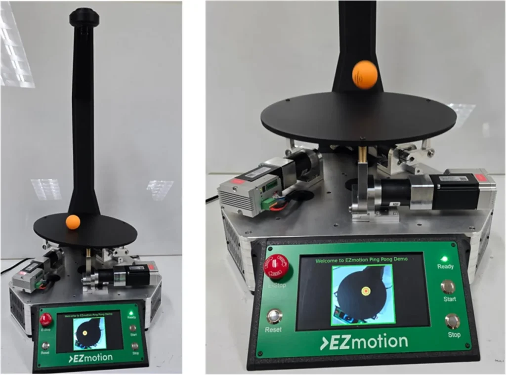
In a significant demonstration of advanced motion control capabilities, a sophisticated parallel-kinematics platform has been engineered to precisely manipulate a ping-pong ball in real time, showcasing the unparalleled performance of a new line of integrated servomotors. This innovative system combines synchronized servo actuation with visual feedback and rapid kinematic computation to achieve dynamic balancing, swirling, and bouncing of the lightweight, often unpredictable ball. The development highlights crucial advancements in precision engineering, offering a glimpse into future applications across various industrial and medical sectors where instantaneous response and high-resolution motion are paramount.

The Demonstration Platform: A Showcase of Precision
At the heart of this technological showcase is a three-axis parallel platform designed to push the boundaries of real-time control. Unlike traditional serial manipulators, parallel kinematic machines (PKMs) offer advantages in rigidity, speed, and accuracy due to their closed-loop structure, where multiple kinematic chains connect the base to a single end-effector (in this case, the platform surface). This inherent stability makes them ideal for tasks demanding high dynamic performance and precise force application, even if their workspace is typically smaller. The challenge of controlling a ping-pong ball – a seemingly simple object – is deceptively complex. Its minimal mass and high coefficient of restitution mean it reacts drastically and chaotically to the slightest disturbance, requiring an exceptionally responsive and accurate control system to maintain its desired trajectory.

The platform’s design integrates several critical technologies: advanced servomotors with onboard drivers, high-resolution angle sensors, and robust CANopen support. These components collectively enable the system to achieve high-resolution motion, deliver real-time response, and ensure tight multi-axis synchronization. Key technical hurdles addressed by this setup include managing visual-feedback latency, maintaining precise synchronization across all three axes, and executing real-time inverse kinematics and proportional-integral-derivative (PID) control on embedded hardware. Charan Bhamra, a Mechatronics Engineer at Monolithic Power Systems, whose work is central to such innovations, underscores the complexity and ingenuity involved in harmonizing these diverse elements.
The Integrated Servomotor at the Core

The success of the parallel platform hinges on the performance of the integrated servomotors, specifically the EZmotion MMS740100-24-C2-1 model. These 40-mm smart motors represent a significant leap in motor design, integrating a permanent-magnet synchronous motor with a sophisticated driver module. This compact, all-in-one solution dramatically simplifies system architecture and wiring, embodying a true plug-and-play philosophy for motion control applications.
Each motor incorporates a built-in servo driver, efficiently supplying power to the motor windings, and an embedded motion controller that runs a nested control loop. This internal controller meticulously regulates current, velocity, and position in real time, ensuring optimal performance. A 14-bit resolution magnetic position sensor tracks the shaft’s position with sub-degree accuracy, providing the critical feedback necessary for precise control. Furthermore, the onboard CAN transceiver facilitates direct integration into a CANopen network, a standardized communication protocol widely adopted in industrial automation for its reliability and deterministic behavior. A dedicated power management solution ensures stable internal voltages, safeguarding operation and enhancing longevity. By consolidating the sensor, driver, controller, communication interface, and power management into a single device, these servomotors eliminate the need for external boards and controllers, reducing component count, cost, and overall system complexity for designers and integrators.

Realtime Control Architecture: Bridging Vision and Motion
The control system’s architecture cleverly distributes computational roles between a Raspberry Pi 5 device and a Cortex M4 microcontroller unit (MCU). This separation of concerns optimizes processing power where it’s most needed. The Raspberry Pi 5, known for its robust processing capabilities and rich ecosystem, handles the intensive visual feedback processing. It runs a lightweight Python script leveraging OpenCV, an open-source computer vision library, to process video frames from a top-mounted USB camera at a moderate yet effective rate of 40 frames per second.

For accurate ball tracking, Gaussian blur is applied to the video frames to reduce noise, and the images are then converted to the Hue, Saturation, Value (HSV) color space. The ping-pong ball, featuring an orange color mask, is identified by applying specific color filters. Contour filtering helps to delineate the ball’s boundaries, and its precise center coordinates in the XY plane are extracted from the smallest circle that completely encloses the largest contours. The ball’s Z-position (height) is ingeniously determined by its apparent diameter in pixel units; as the ball approaches the camera, its detected diameter increases, and this pixel information is translated into a real-world Z-position in millimeters. The Raspberry Pi also offers a live rendering of the camera feed with post-processed ball tracking frames on a local HDMI display, providing immediate visual feedback. This crucial position and height data is then relayed to the Cortex M4 MCU via a high-speed Serial Peripheral Interface (SPI) communication link.
The Cortex M4 MCU acts as the central initiator controller for the motors. It is responsible for the platform’s core control loop and kinematic model. The core control is built around a PID-based algorithm, a ubiquitous feedback control mechanism in industrial systems. This algorithm continuously calculates the difference between the desired and actual ball position (positional error) and uses this error to compute a precise platform tilt angle. A well-tuned PID controller can significantly reduce steady-state error, minimize overshoot, and improve system responsiveness, which is vital for dynamic tasks like ball balancing.

Kinematic Modeling: The Brains Behind the Movement
The precision of the platform’s motion is fundamentally governed by its kinematic model, specifically an inverse kinematic approach. This model calculates the required motor crank angles to achieve a target platform tilt angle and Z-translation. The process begins with defining the global positions of the fixed-base joints and the local positions of the moving platform joints, which are distributed on a circle of a given radius.

Rotation matrices are then employed to define how the platform moves in three-dimensional space. These matrices describe rotations around the X, Y, and Z axes by specific angles. A combined rotation matrix then articulates the platform’s axes relative to the base’s axes. With these definitions, the actual positions of each platform joint in global coordinates can be determined. Once these global joint positions are established, the needed length of each limb is calculated as the straight-line distance between its base joint and the corresponding transformed platform joint. Finally, based on the required length of each limb and the known lengths of the crank arm and connecting rod, the precise motor crank angle for each servomotor is computed. These complex mathematical transformations are executed in real time by the MCU, enabling the platform to respond instantaneously to changes in the ball’s position. Visual aids, such as 3D and 2D views of the manipulator’s limbs, help to illustrate the intricate linkage geometry and how these equations translate into physical motion.
Dynamic Control Modes: Mastering the Ping-Pong Ball

The MCU’s PID-based control system continuously adjusts the platform’s tilt and Z-translation to manage the ball’s motion. The demonstration features three distinct modes, each with its own independent PID controller to achieve specific behaviors:
-
Balancing: In this mode, the objective is to keep the ping-pong ball fixed at the center of the platform. The PID controller constantly works to minimize the positional error by adjusting the platform’s tilt angles (θx and θy) accordingly, countering any movement of the ball away from the center.

-
Circular Swirling: Here, the target trajectory is a predefined circular path with a 100mm radius in the XY plane. The PID controller guides the platform to follow this time-varying reference, causing the ball to swirl in a continuous circle.
-
Bouncing: This mode aims to maintain the ball at a target height at the center of the platform. To initiate bouncing, the system enters an oscillation phase, where the platform undergoes rapid vertical movement to impart sufficient energy to lift the ball off the surface. This phase gradually increases the ball’s mechanical energy. Once a predefined energy threshold is reached (indicating consistent bouncing), the controller transitions to a sustained bouncing mode. In this phase, the controller applies minimal synchronized vertical motion, optimizing energy efficiency while maintaining the desired bounce height. The ball’s total energy is estimated using both kinetic and potential energy components, with velocity computed from the difference between current and previous ball heights over the timestep.

CANopen and Synchronized Actuation
A cornerstone of the platform’s precision is the use of CANopen’s Cyclic Synchronous Position (CSP) mode for motor control. CANopen, an application layer protocol built on the Controller Area Network (CAN) bus, is renowned for its determinism and robust communication capabilities in automation. While other CANopen modes, such as Cyclic Synchronous Velocity (CSV) and Cyclic Synchronous Torque (CST), are suitable for velocity and torque-driven applications, CSP mode is specifically designed for deterministic, position-based multi-axis control, making it ideal for the synchronized movements required by the parallel platform.

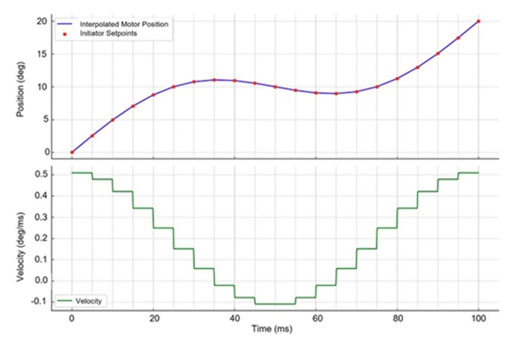
In CSP mode, the MCU, acting as the initiator, sends precise position setpoints to each motor at a fixed and deterministic update rate. To ensure continuity and smoothness between these discrete updates, each motor internally performs linear interpolation between consecutive setpoints. This means the motor controllers do not generate their own complex trajectories; instead, they rely on the central MCU to continuously feed updated position targets. From a communication perspective, CSP mode requires the initiator to send Process Data Object (PDO) messages containing these absolute target positions. PDOs are highly efficient, low-latency messages in CANopen. These PDOs can be mapped, configured, and stored in the motor’s non-volatile memory. The calculated crank angle values from the inverse kinematics are converted into CSP position targets and broadcast synchronously across the CAN bus, ensuring highly coordinated and jitter-free motion across all three limbs of the platform.
Operational Sequence and User Experience

The demonstration sequence is meticulously choreographed to highlight the system’s capabilities. It begins with a torque-based homing routine for the servomotors. During this process, all three limbs retract inward at a controlled speed until they reach their mechanical hard stops, establishing a repeatable and precise zero position. Once homing is successfully completed, the platform automatically rises to a predefined mid-height along the Z-axis. A green status LED illuminates, signaling successful initialization and indicating that a user can safely place a ping-pong ball on the platform.
The manipulator then enters its active sequence, starting with the balancing mode to stabilize the ball. After a predetermined period, it transitions to the circular swirl mode, which it executes for 30 seconds. This is followed by the bouncing mode, also lasting 30 seconds. This sequence continuously loops, showcasing the system’s ability to seamlessly switch between complex control tasks as long as it remains active. Throughout the demonstration, a 7-inch screen provides live visual feedback of the ball’s motion, allowing observers to appreciate the precision of the tracking and control.

Beyond the Demo: Real-World Applications and Future Outlook
While the ping-pong ball demonstration is an engaging and effective way to showcase precision motion control, the underlying technologies have profound implications for real-world applications across numerous industries. The ability to achieve fine resolution, real-time response, and jitter-free multi-axis synchronization with integrated servomotors is a game-changer.

In medical robotics, similar parallel kinematic architectures are already being implemented to stabilize endoscopic instruments, guide surgical tools with sub-millimeter precision, and assist in minimally invasive procedures. The demand for enhanced accuracy and reduced invasiveness in surgery makes these technologies invaluable. For example, robotic surgical platforms often rely on high-precision servomotors and sophisticated control algorithms to translate a surgeon’s macroscopic movements into microscopic, steady actions within the patient’s body.
In industrial automation, integrated servomotors like those demonstrated here are crucial for tasks demanding extreme precision. They impart motion to optical alignment stages, where components must be positioned with nanometer accuracy; to pick-and-place heads in electronics manufacturing, requiring high speed and repeatability; and to micro-assembly manipulators, dealing with components smaller than a grain of sand. Delta 3D printers and certain pick-and-place machines frequently utilize servo-driven parallel kinematic structures due to their speed and dexterity. The compact nature and simplified wiring of integrated servomotors also contribute to more streamlined machine designs, faster deployment, and reduced maintenance.
Industry analysts suggest that the trend towards increasingly integrated and "smart" motion control components, such as those from EZmotion, will continue to accelerate. These solutions not only reduce the bill of materials and assembly time but also enhance system reliability by minimizing external connections and potential points of failure. The ability to manage complex control loops and communication protocols like CANopen within the motor itself empowers engineers to design more efficient, compact, and high-performance machines. As manufacturing processes become more intricate and the demand for personalized products grows, the need for such precise and adaptable motion control solutions will only intensify, pushing the boundaries of what automated systems can achieve. The ping-pong ball platform, therefore, is not merely a clever trick but a tangible proof of concept for the next generation of intelligent robotic systems.