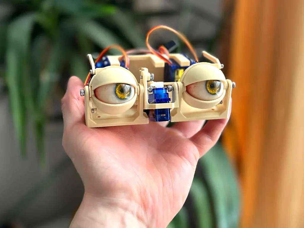
The burgeoning field of animatronics continues to push the boundaries of mechanical realism, with expressive robotic eyes standing as a cornerstone of believable human-robot interaction and immersive entertainment. A recent detailed construction guide, offering an intricate look into the assembly of animatronic eye mechanisms, underscores the growing sophistication and accessibility of DIY robotics projects. This particular endeavor meticulously outlines the sequential steps for integrating multiple servo motors and custom-fabricated components to achieve nuanced eye and eyelid movements, providing a tangible example of the complex interplay between mechanical design and electronic control that defines modern animatronics.
The Evolution of Expressive Robotics
Animatronics, a portmanteau of "animated" and "electronics," has roots tracing back to the early 20th century, but it was Walt Disney Imagineering that truly popularized the art form, starting with the Enchanted Tiki Room in 1963 and the iconic Abraham Lincoln figure at the 1964 New York World’s Fair. These early figures, while revolutionary, relied on pneumatic and hydraulic systems, often large and complex. The digital revolution, miniaturization of components, and advancements in 3D printing have democratized animatronics, shifting it from the exclusive domain of large studios to the hands of hobbyists, educators, and independent creators. Expressive eyes are particularly critical in this evolution, as they are often the first point of emotional connection and convey a vast array of non-verbal cues, making a robot or character feel more "alive." The ability to replicate natural eye saccades, blinks, and gazes is paramount for creating convincing synthetic life.

Deconstructing the Animatronic Eye Mechanism: Foundational Principles
The core of any animatronic eye system lies in its ability to mimic the natural movement of biological eyes, which typically involve two primary axes of rotation: horizontal (x-axis) and vertical (y-axis). Additionally, the integration of dynamic eyelids adds another layer of realism, allowing for blinking, winking, and subtle expressions that significantly enhance believability. The project detailed in the construction guide showcases a robust approach to achieving these movements through a combination of precisely engineered components and carefully selected actuators.
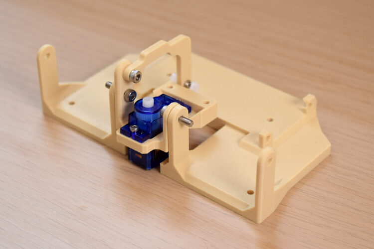
The initial phase of assembly focuses on establishing the fundamental mechanical linkages. Connecting two primary bases using 10mm or 12mm M3 bolts is not merely a fastening step; it creates the crucial pivot point for the y-axis motion. This single pivot is ingeniously designed to govern both the vertical movement of the eye itself and the coordinated motion of the eyelids, highlighting an economical use of mechanical resources to achieve multiple functions. The choice of M3 bolts, a standard size in hobbyist robotics, suggests a balance between strength and the compact nature required for animatronic components.
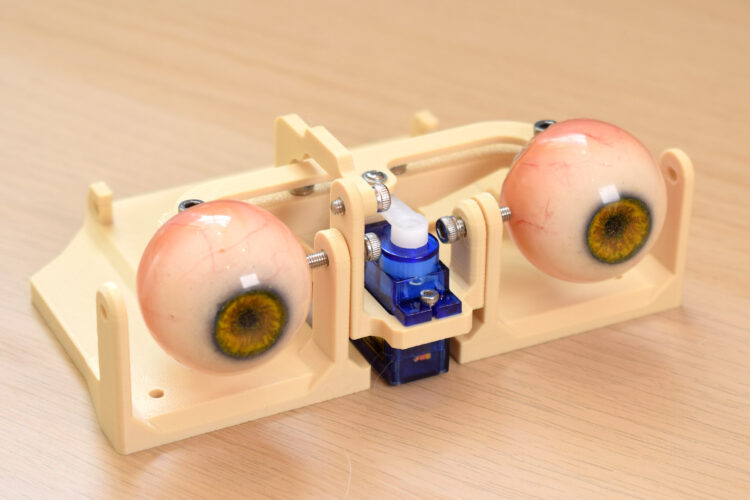
Following the establishment of the y-axis pivot, the system introduces the primary actuator for the x-axis motion. A compact servo motor is strategically positioned and secured with 4mm or 6mm M2 screws. Servo motors, particularly models like the TowerPro SG90 mentioned later, are ideal for such applications due to their precise angular control and relatively small form factor. Their ability to hold a specific position and respond rapidly to commands makes them indispensable for dynamic eye movements. The choice of M2 screws indicates the small scale and precision required for mounting these delicate components without compromising structural integrity.
The Assembly Workflow: A Step-by-Step Chronicle
The construction proceeds with a methodical assembly, each step building upon the last to create a fully articulated system.
1. Y-Axis Linkage and Servo Horn Attachment: The y-axis arm is affixed to a sub-base using a 4mm, 5mm, or 6mm M3 screw. This connection is critical for transmitting the servo’s rotational force into vertical eye movement. Subsequently, a servo horn is attached to the third hole from the center of this arm with a 4mm or 6mm M2 screw. The specific placement on the servo horn dictates the leverage and range of motion, requiring careful consideration during design. Emphasizing the need to "check to make sure the orientation of everything is right" underscores the iterative nature of animatronics design, where precise alignment is paramount to prevent binding or incorrect movement.
2. X-Axis Assembly Initiation: The horizontal movement mechanism begins with screwing the "forks" into "eye-adaptors" using 4mm, 5mm, or 6mm M3 bolts. The design specifies oversized holes in the forks, allowing the screws to "bite" into the adaptor material, likely a 3D-printed plastic, to create a secure, self-tapping connection. The acknowledgement that "one goes in on a funny angle but you should be able to get it in" points to the minor tolerances and practical challenges often encountered in DIY fabrication, requiring a degree of dexterity and problem-solving from the builder.
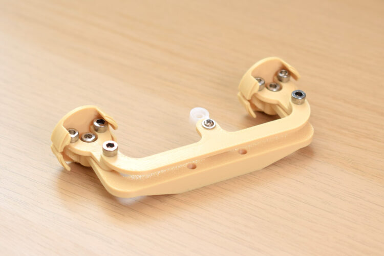
3. Three-Point Connector and X-Axis Servo Arm: A three-point connector is then attached to the top of the forks, again utilizing M3 screws that engage with undersized holes for a tight fit. Crucially, a servo arm is attached to the final hole at the center of this three-point connector using a 5mm M3 bolt. A key detail here is the potential necessity to drill the servo arm’s hole to a larger diameter (2.5mm–2.8mm) to accommodate the screw. This modification highlights a common practice in DIY projects where off-the-shelf components may require minor adjustments for perfect integration. The recommendation to "manipulate the assembly regularly as you build it up, to make sure it all moves OK without friction" is invaluable advice, stressing the importance of continuous testing to ensure smooth operation and prevent mechanical strain.
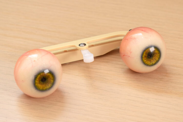
4. Eye Integration and Central Linkage: The "eye center-link" is connected to the eye adaptors with an 8mm M3 screw. Specific orientation is crucial here: the flat surface of the center-link must face upwards, and the sloping section downwards, indicating a design choice for optimal articulation or aesthetic integration. At this stage, the actual eyes – often 3D-printed spheres or commercial doll eyes – are plugged into their respective adaptors, making the mechanism visually recognizable.
5. Sub-Base Integration: The entire x-axis assembly, complete with eyes, is then securely fastened to the center of the sub-base using two 12mm M3 bolts. This step integrates the independent eye movement mechanism into the broader frame that will be driven by the y-axis servo.
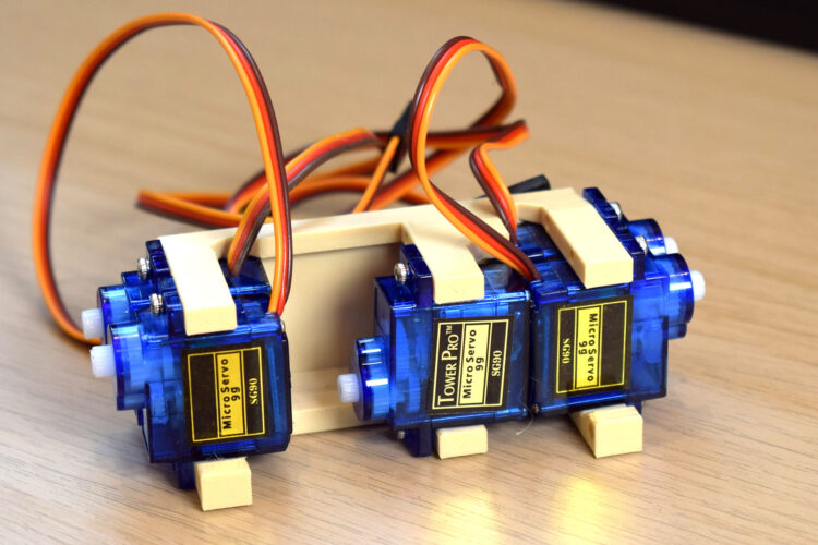
6. Servo Block Loading and Base Attachment: A critical component, the "servo block," is loaded with five TowerPro SG90 servos. The correct orientation of these servos is emphasized, as their precise alignment is vital for the intended range of motion and linkage connections. Once loaded, the servo block is attached to the main base with four M3x10mm bolts, establishing the complete set of actuators for the system. The TowerPro SG90 is a ubiquitous micro servo in the hobby robotics world, known for its affordability and sufficient torque for small-scale animatronics, making it a popular choice for accessible projects.
7. Eyelid Assembly and Linkages: The final stage focuses on the intricate eyelid mechanism. The guide instructs builders to identify the correct eyelids using a reference photo, then connect them to their respective connectors with 4mm or 6mm M2 screws. A servo arm is then attached to the other end of these connectors, utilizing the last hole in the servo horn. Similar to previous steps, drilling this hole to a smaller diameter (1.5mm–1.8mm) might be necessary, again highlighting the need for minor component customization.
8. Eyelid Attachment to Base: The eyelids are finally attached to the base. The instruction to "don’t worry about connecting any servo horns yet" suggests that the final calibration and connection of the eyelid servos to their respective arms will be a separate, perhaps software-driven, alignment process, common in animatronics to ensure synchronized and natural movement.
Precision Engineering: The Role of Components and Materials
The consistent use of M2 and M3 bolts and screws throughout the build underscores a commitment to standardized, readily available components, crucial for DIY projects. The differing lengths (4mm, 6mm, 8mm, 10mm, 12mm) indicate varying material thicknesses and structural requirements at different connection points. The mention of "oversized holes" for screws to "bite into" components strongly suggests the use of 3D-printed parts, a hallmark of modern maker culture. 3D printing allows for rapid prototyping and the creation of custom geometries perfectly tailored for specific mechanical functions, such as the eye-adaptors, forks, and connectors. The TowerPro SG90 servos, as mentioned, are entry-level but highly capable micro servos, ideal for educational and hobbyist projects due to their balance of cost, size, and performance.
Broader Implications and Future Outlook
This detailed construction guide for animatronic eyes serves as more than just a set of instructions; it represents a significant step in the democratization of complex robotic systems. By breaking down the intricate process into manageable steps, coupled with specific component recommendations, it empowers hobbyists and students to engage with advanced engineering concepts. This accessibility fuels innovation, as more individuals gain the skills to experiment and contribute to the field.
The implications extend across several sectors:
- Education: Such projects provide invaluable hands-on learning experiences in mechanics, electronics, programming, and design. They bridge theoretical knowledge with practical application, fostering critical thinking and problem-solving skills vital for STEM fields.
- Entertainment and Arts: Independent filmmakers, theater productions, and artists can create more compelling and realistic characters without the prohibitive costs associated with commercial animatronics. This opens new avenues for creative expression and storytelling.
- Human-Robot Interaction (HRI): The development of expressive animatronic eyes is directly applicable to creating more natural and empathetic human-robot interactions. Robots with believable facial expressions and eye movements are perceived as more trustworthy and engaging, which is crucial for applications in healthcare, customer service, and companionship robotics.
- Prosthetics and Assistive Devices: The underlying principles of compact, multi-axis movement could inform the design of more sophisticated and aesthetically integrated prosthetic devices, particularly those involving facial features.
The ongoing advancements in materials science, micro-actuators, and artificial intelligence will undoubtedly lead to even more sophisticated animatronic eyes. Future iterations might incorporate advanced sensors for gaze tracking, machine learning algorithms for autonomous expressive responses, and even more compact, silent, and powerful actuators. The foundation laid by projects like this, however, remains critical – demonstrating that the intricate dance of gears, servos, and carefully chosen fasteners is the beating heart of synthetic life, one expressive blink at a time. The work documented here not only offers a pathway for building impressive animatronic features but also inspires the next generation of engineers and creators to explore the frontiers of robotics and artificial intelligence.