Fractional-horsepower gearmotors are indispensable components in a myriad of industrial and commercial applications, designed to meet highly specific operational demands. Among the various configurations, gearmotors incorporating worm gearing are frequently specified by OEM design engineers, often to harness what is perceived as their inherent "self-locking" characteristic. However, this particular attribute of worm gears is a frequent source of misunderstanding and, consequently, misapplication, leading to significant safety and operational challenges across various sectors. The critical distinction lies in recognizing that the static self-locking behavior of a worm gear is fundamentally different from the active, dynamic braking required to safely decelerate and stop a moving load.
The Mechanics of Worm Gearing and the "Self-Locking" Phenomenon
Worm gears typically consist of a worm (a screw-like shaft) and a worm wheel (a gear resembling a spur gear, but with a throated face to mate with the worm). This arrangement provides a high gear ratio in a compact space and offers a unique right-angle power transmission. The "self-locking" property arises from the geometry of the worm and wheel, specifically the lead angle of the worm and the friction between the mating surfaces. When the lead angle is small (typically less than 5 degrees) and the coefficient of static friction between the worm and wheel is sufficiently high, the worm wheel cannot back-drive the worm. This means that if power to the motor is removed, the load on the worm wheel will not cause the worm to rotate backward, effectively holding the system in a static position.
This characteristic is a consequence of the mechanical efficiency of the worm gear. In a worm gear, power transmission from the worm to the wheel is generally efficient, but power transmission in the reverse direction (from the wheel to the worm) can be very inefficient, sometimes so much so that it becomes impossible. This irreversibility is what gives rise to the self-locking phenomenon. It’s a passive resistance to motion from the load side when the input (worm) is not driven.

Distinguishing Static Self-Locking from Dynamic Braking
The core of the misunderstanding lies in equating static self-locking with dynamic braking. Dynamic braking refers to an electromechanical system’s active ability to slow down or stop an axis that is currently in motion. This process involves dissipating kinetic energy, often through friction (as in mechanical brakes), electromagnetic forces, or by converting the motor into a generator that feeds energy back into resistors or the power grid (regenerative braking). A true dynamic brake is engineered to absorb and dissipate the kinetic energy of a moving load, bringing it to a controlled, predictable stop within a specified time or distance.
In contrast, the self-locking behavior of worm gears only manifests once the system has already ceased motion. If a worm gearmotor-driven axis is in motion and electrical power is removed, the inertia of the moving load will continue to drive the system forward. The worm gear, in this dynamic state, cannot inherently dissipate the kinetic energy to bring the axis to a quick stop. It will only "lock" once the system has slowed down sufficiently, often through natural friction and drag, and then attempts to back-drive from a static position. Therefore, relying on a self-locking worm gear for dynamic braking in an application requiring controlled deceleration is a critical design flaw.
The Perilous Roots of Misapplication
The misconception often stems from an intuitive but incorrect leap of logic: "If a gearbox is self-locking, it must stop the load when power is cut." This oversimplification overlooks the fundamental physics of motion and energy dissipation. The term "self-locking" itself, while technically accurate for static conditions, can be misleading in the broader context of motion control. For OEM design engineers, specifying components solely based on a perceived characteristic without fully understanding its limitations can lead to severe consequences.

The implications of this misapplication are far-reaching. At best, it can lead to inefficient operation or premature wear on components. At worst, it creates significant safety hazards, risking injury to personnel or damage to valuable equipment and products. For example, a system designed to rapidly stop a heavy, moving load using only a self-locking worm gear would fail to do so, allowing the load to coast dangerously.
The Indispensable Role of Dedicated Braking Systems
For applications requiring precise and safe stopping, dedicated braking systems are essential. These can take various forms:
- Electromechanical Brakes: These are common in industrial settings. Often "power-off" or "fail-safe" brakes, they are spring-applied when power is removed and electrically released when power is applied. They physically clamp onto a rotating shaft, using friction to dissipate kinetic energy and hold the load.
- Dynamic Braking Resistors: For electric motors, particularly DC motors or AC servo motors, dynamic braking can be achieved by short-circuiting the motor windings through a resistor when power is cut. The motor then acts as a generator, converting kinetic energy into electrical energy, which is dissipated as heat in the resistor, bringing the motor to a controlled stop.
- Regenerative Braking: A more advanced form of dynamic braking where the motor, acting as a generator, feeds the generated electrical energy back into the power supply or a capacitor bank, improving energy efficiency.
- Hydraulic or Pneumatic Brakes: Used in heavy machinery, these systems use fluid pressure to engage braking mechanisms.
The most effective and safest designs often integrate a dedicated brake with a self-locking gearbox. The brake performs the crucial function of dynamic deceleration and stopping, dissipating the kinetic energy of the moving load. Once the load has come to a complete stop, the self-locking worm gear then takes over, providing a secure, passive hold, preventing any back-driving or drift, even if power is completely removed. This synergistic approach ensures both dynamic safety and static stability.
Real-World Applications Illustrating the Distinction

Consider the following examples, which highlight the critical need for proper component selection:
-
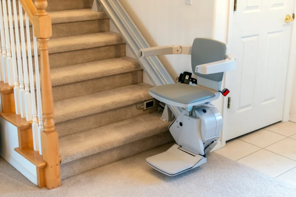
Stair Lifts for Mobility Applications: These systems transport individuals up and down staircases, often in residential or public settings. Safety is paramount. When a user reaches their destination or in an emergency, the lift must come to a rapid, controlled stop. A dedicated brake is absolutely essential here to decelerate the carriage smoothly and quickly, preventing overshooting or dangerous jolts. Once stopped, the self-locking worm gearbox then maintains the lift’s position securely, even during a power outage, preventing any downward creep or freefall. This combination ensures passenger safety, adhering to stringent accessibility and safety standards (e.g., ASME A17.1/CSA B44 for elevators and escalators, which includes specific requirements for braking and holding mechanisms). Bodine Electric Co., for instance, designs PMDC gearmotors for such applications, emphasizing the need for an integrated brake for dynamic stopping and a self-locking gearbox for static holding.
-
Commercial Rotisserie Ovens: In professional kitchens, rotisserie ovens cook poultry or other meats by slowly rotating them. If an oven door is opened for inspection or removal, the rotation must immediately cease to prevent burns to personnel and ensure precise handling of the product. The inertia of the rotating spit, especially with an imbalanced load (e.g., two chickens on one side, none on the other), could cause it to continue turning due to gravity. Here, a quick-acting brake is required to bring the rotisserie spits to an instantaneous, full stop. Following this, the self-locking worm gearbox ensures that the spits remain in that exact, safe position, preventing any unwanted rotation due to imbalance or external forces while the oven door is open.
-
Industrial Conveyors and Hoists: In manufacturing and logistics, conveyor belts and hoists move heavy materials. Stopping these systems quickly and accurately is crucial for operational efficiency and worker safety. A sudden stop might be needed for emergency situations, precise positioning, or preventing collisions. Relying solely on a worm gear’s self-locking property would be insufficient; the conveyor or hoist would coast for a dangerous distance. Instead, robust braking systems are integrated to provide controlled deceleration, and then the self-locking gear provides the static hold, preventing heavy loads from drifting or falling when stationary.
When Backdrivability Becomes a Critical Requirement

Paradoxically, some applications demand the exact opposite of self-locking: full backdrivability. While engineers may not explicitly request "backdrivable gearing," the underlying need for low resistance to back-driving is frequently expressed in other functional requirements. This highlights the nuanced nature of gearmotor selection.
-
Railroad Crossing Gates: These critical safety systems have extremely strict requirements for their operation, particularly in failsafe scenarios. In the event of a power failure, the gates must fall down and block vehicle traffic to prevent collisions with oncoming trains. This mechanism relies on gravity. To achieve this, the gearbox driving the gate arm must be easily backdrivable, meaning the weight of the arm alone, or the arm with minimal counterbalancing, can overcome the internal resistance of the gearbox and bring the arm down into its safe, closed position. The design is often complicated by counterweights used to allow a relatively small, low-power motor to lift the heavy arm. The entire system is engineered for gravity-assisted failsafe operation, necessitating a highly efficient, easily reversible gearbox, typically involving helical or spur gears rather than worm gears.
-
Parking Barrier Gates: Similar to railroad gates, parking garage barrier arms often need to be backdrivable. If there’s a power failure, a ticket system malfunction, or an emergency, an attendant or emergency personnel might need to manually lift the gate. This functionality requires an electromechanical assembly, including the motor’s gearbox, that offers minimal resistance to manual force, allowing it to be easily back-driven. Alternatively, some systems incorporate electronic overrides or mechanical clutches, but the inherent backdrivability of the gearbox simplifies the failsafe design and manual intervention.
Industry Best Practices and the Call for Clarity
Given the pervasive confusion, some manufacturers have begun to de-emphasize the unqualified term "self-locking" when describing worm gearmotor behavior. Instead, they provide detailed specifications on static holding torque and differentiate it clearly from dynamic braking capabilities. This shift towards more precise terminology is crucial for avoiding dangerous misinterpretations.

Industry experts, such as Terry Auchstetter of Bodine Electric Co., consistently advise OEM design engineers to engage in thorough consultation with gearmotor manufacturers. This collaborative approach ensures that the chosen components align perfectly with the application’s specific requirements, considering both dynamic and static operational phases, as well as crucial failsafe scenarios. Adherence to international and national safety standards (e.g., ISO, ANSI, OSHA, UL) is also paramount in designing motion control systems. These standards often mandate specific braking and holding capabilities for equipment handling loads or interacting with personnel.
Broader Implications for Motion Control Design
The distinction between static self-locking and dynamic braking is not merely a technicality; it has profound implications across the entire spectrum of motion control design:
- Enhanced Safety: Correct application prevents uncontrolled motion, reducing the risk of injuries, equipment damage, and catastrophic failures. This is particularly vital in fields like medical devices, robotics, and industrial automation where human-machine interaction is frequent.
- Optimized Performance: Proper component selection ensures that systems operate as intended, achieving desired stopping times, positional accuracy, and overall efficiency without unnecessary strain on components.
- Reduced Costs: Avoiding misapplications prevents costly redesigns, emergency repairs, downtime, and potential legal liabilities stemming from accidents.
- Regulatory Compliance: Understanding these distinctions is crucial for meeting stringent industry regulations and safety certifications, which often dictate specific braking and holding requirements.
- Fostering Innovation: A clear understanding of mechanical principles allows engineers to push the boundaries of design, creating safer, more reliable, and more efficient machines.
In conclusion, while the self-locking characteristic of worm gearmotors offers significant advantages for static holding in many designs, it is imperative for design engineers to understand that this behavior is distinct from dynamic braking. A self-locking worm gear will hold a load once it’s already stopped, but it cannot actively slow down a moving load. For applications requiring controlled deceleration and stopping, a dedicated braking mechanism is indispensable. The careful selection and integration of both components, guided by expert advice and a rigorous understanding of motion physics, are fundamental to developing safe, efficient, and reliable motion control systems.