This primer delves into the foundational elements underpinning automated motion systems, whether integrated into sophisticated robotics or purpose-built machinery designed for precise, repetitive tasks. Understanding these core principles is essential for engineers and designers aiming to optimize performance, reliability, and efficiency in a wide array of industrial and consumer applications.
The Core Principles of Motion Systems
At their heart, all motion systems are electric-motor-driven designs constructed from two primary categories of components: mechanical and electrical/control. The interplay between these elements dictates a system’s ability to achieve desired movements and positions.
Mechanical Components: These are the physical structures and mechanisms that transmit power and facilitate movement. They include:
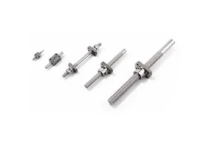
- Power Transmission Elements: Gears, belts, pulleys, chains, sprockets, leadscrews, ballscrews, and roller screws.
- Linear and Rotary Guides: Bearings, linear rails, and bushings that ensure smooth, precise motion along defined paths.
- Structural Elements: Frames, housings, and mounting hardware that provide rigidity and support.
- Actuators: Beyond the motor itself, these include components like linear actuators, rotary tables, and robotic arms that perform the actual work.
Electrical and Control Components: These are the "brains" and "nervous system" that power, command, and monitor the mechanical components. They encompass:
- Electric Motors: The prime movers, converting electrical energy into mechanical energy (e.g., servo motors, stepper motors, DC motors).
- Motor Drives (Amplifiers): Electronics that regulate the power supplied to the motors based on control signals.
- Motion Controllers: The central processing units that interpret commands, generate motion profiles, and manage feedback.
- Sensors and Encoders: Devices that provide real-time feedback on position, velocity, and other critical parameters.
- Wiring and Connectivity: Cables, connectors, and communication protocols that link all components together.
The motion industry often distinguishes between power-transmission designs and motion systems. Power-transmission designs typically emphasize raw torque or force and speed, with a dominance of mechanical components focused on delivering power. Examples include heavy-duty conveyors or simple rotational drives where precise positioning is less critical than brute force and sustained speed.
In contrast, motion systems prioritize precise positioning and controlled motion profiles. These systems meticulously define speeds, accelerations, jerk, speed-torque profiles, and homing routines for a machine’s various axes. This distinction is crucial for applications demanding high accuracy and repeatability, where the control elements play an equally, if not more, vital role than the mechanical power delivery. The evolution of industrial automation has increasingly leaned towards the latter, driven by demands for higher precision and greater flexibility.
The Realm of Automation: Discrete vs. Process
Both power-transmission and motion systems are indispensable in a vast array of applications, from everyday consumer products and office automation equipment to advanced medical devices, laboratory automation, and complex industrial machinery. Within the industrial space, a key distinction exists between discrete factory automation and process (or analog) automation.

Discrete factory automation involves the handling, machining, assembling, testing, capping, wrapping, packaging, labeling, counting, scanning, and transporting of individual, separate workpieces or products. Each item may undergo multiple distinct operations before completion. This type of automation is characterized by distinct starts and stops, precise movements, and the manipulation of individual units. Industries reliant on discrete automation include:
- Automotive Manufacturing: Assembly lines, robotic welding, paint shops.
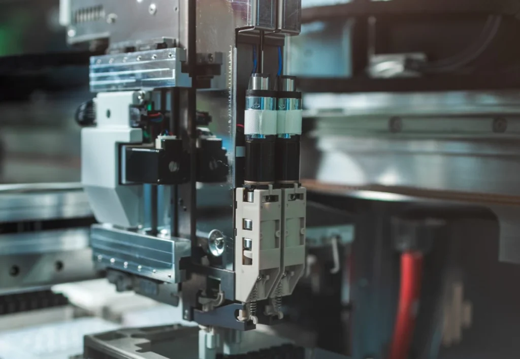
- Electronics Production: Pick-and-place machines for circuit boards, semiconductor manufacturing.
- Automated Warehousing and Logistics: Robotic material handling, automated guided vehicles (AGVs), sorting systems.
- Packaging: Filling, sealing, labeling, and palletizing individual products.
- Machine Tools: CNC machining centers, additive manufacturing systems.
Motion system designs are intrinsically linked to discrete automation, as they are specifically engineered to deliver the precise placement and transport of these individual workpieces or products. The demand for speed, accuracy, and flexibility in these sectors continues to drive innovation in motion control technology.
In contrast, process automation deals with continuous flows, batches, and uninterrupted systems. This typically involves vats of liquids, extensive piping networks, and processes subject to continuous chemical reactions, temperature controls, metering, and flowing operations that are difficult to stop and start. Process automation industries include:
- Mining: Ore processing, material conveyance.
- Energy: Power generation (coal, nuclear, renewables), oil and gas extraction and refining.
- Food Processing: Continuous cooking, mixing, bottling, and pasteurization.
- Pharmaceutical and Chemical Manufacturing: Batch processing, continuous reactor control.
- Glass and Ceramic Production: Kiln control, material flow.
- Plastics, Textiles, Wood, and Paper: Continuous sheet production, fiber processing.
While process automation employs various control systems, its focus is on maintaining continuous parameters rather than the precise, discrete movements characteristic of motion systems.
The Foundational Design Process: Loads, Inertia, and Torque
The journey of designing an automated motion system typically commences with a thorough documentation of the loads to be moved and the inertias involved. This crucial initial step also requires quantifying the friction the motorized axis must overcome without introducing unacceptable sluggishness or instability.
Inertia, defined as an object’s resistance to changes in speed (acceleration or deceleration), is a paramount consideration. The total inertia within a system comprises the inertia of the workpiece load, the moving parts of the axis itself, and any reflected inertia from mechanical transmission components.
- Low Inertia Systems: Direct-drive motors (e.g., torque motors, linear motors) often exhibit very low reflected inertia as they eliminate intermediate mechanical components. This allows for highly dynamic responses.
- High Inertia Systems: Systems incorporating gearsets for speed reduction or mechanical power transmission elements like belt-and-pulley, rack-and-pinion, or chain-and-sprocket sets will have higher reflected inertia. These "tangential forms of power transmission" introduce their own inertia, which must be factored into the motor sizing. Similarly, linear actuators utilizing leadscrews, ballscrews, or roller screws also contribute significantly to the overall system inertia.
Engineers must meticulously sum all the axis components’ inertias and calculate what is reflected back to the axis’s motor-output shaft. This calculation is critical for proper motor sizing and system tuning. A particularly challenging scenario arises with changing inertia loads, such as robotic axes performing dispensing tasks where the payload weight diminishes over time, or machining tasks where material is removed. In these instances, the motion controls may require advanced servotuning algorithms, often adaptive, to compensate for the dynamic changes in system inertia, ensuring consistent performance and preventing oscillations.

Once the mechanisms, their friction, and inertia are accurately quantified, the next critical step is to define the required motor output force (for linear motors) or, more commonly, torque (for rotary motors). This allows for the proper sizing of the electric motor for each axis. A servo axis’s motor must deliver sufficient torque not only for acceleration but also for sustained operation throughout the entire move profile. This includes:
- Acceleration Torque: The peak torque required to overcome inertia and friction to reach the desired speed.
- Constant Torque (Run Phase): The torque needed to maintain speed against friction and external forces during the steady-state portion of the move.
- Deceleration Torque: The torque required to bring the load to a controlled stop, which can sometimes be regenerative, feeding energy back into the drive.
Accurate torque calculations are vital to prevent undersizing (leading to poor performance, overheating, or failure) or oversizing (leading to unnecessary cost and potentially less dynamic response).
The Intelligence Behind Motion: Controls and Drives
The commands that dictate various motor actions originate from system motor controls or motion controls. These two technologies have witnessed significant convergence over the past two decades, often integrated into single, powerful platforms. Both types of electronics accept low-power signals and amplify them to generate the actuation-level electrical output required to drive the motors.
To use a zoological analogy, motion controllers function as the system’s "brains," constantly monitoring, commanding, and integrating a multitude of parameters. They are responsible for:
- Motor Position and Velocity: Tracking the current state of the motor and load.
- Motor Current and Torque: Monitoring power consumption and output force.
- System Inputs: Receiving data from sensors (e.g., proximity switches, vision systems), encoders, and human-machine interfaces.
- System Outputs: Sending commands to actuators, indicators, and other controlled devices.
- Communication: Interfacing with other industrial systems such as Programmable Logic Controllers (PLCs), Human-Machine Interfaces (HMIs), and Supervisory Control and Data Acquisition (SCADA) systems, often via industrial Ethernet protocols.
Like the sophisticated nervous systems of animals, motion controllers can orchestrate complex movements, commanding systems arranged for:
- Point-to-Point Motion: Moving an axis from one defined position to another.
- Interpolated Motion: Coordinating multiple axes to move along a defined path, such as linear interpolation (straight lines) or circular interpolation (arcs).
- Electronic Gearing/Camming: Synchronizing the movement of one axis to another, either with a fixed ratio (gearing) or a complex, non-linear relationship (camming).
- Synchronization of Multiple Axes: Ensuring that several motors move in perfect harmony, critical for robotics and multi-axis machines.
- Path Following: Executing complex, pre-programmed trajectories with high precision.
A key architectural decision in motion system design involves choosing between centralized controls and distributed drive-based controls.
- Centralized Controls: In this traditional setup, the main controller, motors, drives, and complementary electronics are typically housed together in a single control cabinet. This offers advantages in terms of simplified programming and diagnostics for compact machine installations, often leading to economies of scale for smaller systems.
- Distributed Drive-Based Controls: For machines with numerous axes spread over a large area, decentralized motion control can be highly beneficial. Here, drives (which often incorporate some motion control functionality) are located closer to or directly on the motors themselves. This approach can significantly reduce wiring complexity and costs, minimize electromagnetic interference (EMI) issues over long cable runs, and allow for smaller, more manageable control cabinets. The advent of fieldbus technologies and industrial Ethernet has greatly facilitated this distributed architecture.
Regardless of the control architecture, each motor’s drive (be it a dedicated motor control or an integrated amplifier) must possess the capacity to provide sufficient acceleration and continuous current to meet the motion design’s duty-cycle requirements. This includes not only the power to move the load but also the ability to dissipate heat generated during both acceleration and deceleration phases. The Root Mean Square (RMS) current and peak acceleration current are critical metrics, with careful consideration given to any increase in motor winding resistance due to thermal effects.

Precision and Power: The Servosystem Advantage
Motion system designs that operate as closed-loop systems, commonly known as servosystems, represent the pinnacle of precision and dynamic control. These machines are engineered for quick accelerations and decelerations and are capable of operating in all four quadrants of motion. The "four quadrants" concept describes a system’s ability to control an axis across all combinations of positive and negative torques and speeds, meaning it can accelerate, decelerate, run at constant speed, and reverse direction precisely and powerfully.
Sizing such servosystems demands a comprehensive systems approach that concurrently evaluates mechanical, electrical, and software parameters. The drives powering the servomotors must be meticulously selected to deliver all necessary continuous (RMS) and acceleration (peak) currents. This ensures that the motor can respond dynamically to commanded changes, overcoming inertia and friction while maintaining precise control. The feedback loop, comprising sensors and encoders, is fundamental to servosystems, allowing the controller to constantly compare the actual position/velocity with the commanded trajectory and make real-time corrections, thereby minimizing error and maximizing accuracy.
Environmental Resilience and Component Selection
The operational environment of a motion system is a crucial design consideration that directly impacts component selection. Whether a system is destined for hot, dusty, washdown, vacuum, explosive, or other challenging industrial environments, the power-transmission, electromechanical, and electronic components must be chosen for their inherent ruggedness and specific protective ratings.
Key considerations include:
- Ingress Protection (IP) Ratings: These define the sealing effectiveness of enclosures against the intrusion of foreign bodies (like dust and dirt) and moisture. An IP67 rating, for instance, indicates protection against dust ingress and temporary immersion in water.
- National Electrical Manufacturers Association (NEMA) Ratings: Predominantly used in North America, NEMA ratings classify enclosures based on their ability to protect personnel from hazards and internal equipment from environmental conditions (e.g., NEMA 4X for corrosion resistance and washdown, NEMA 7 for hazardous locations).
- Cleanroom Compatibility: For applications in semiconductor manufacturing, pharmaceuticals, or medical device assembly, components must meet strict cleanroom classifications (e.g., ISO Class 1 to 9). This involves using materials that do not shed particles, employing specific lubricants, and designing for minimal outgassing.
- Temperature Extremes: Components must be rated for the expected ambient temperature range, considering both operating and storage conditions.
- Vibration and Shock Resistance: In harsh industrial settings, components must be designed to withstand significant mechanical stress without degradation in performance.
- Corrosion Resistance: Materials like stainless steel or specialized coatings are essential in chemical processing or washdown environments.
- Explosive Atmospheres: For environments with flammable gases or dust, intrinsically safe or explosion-proof components are mandatory, adhering to standards like ATEX or IECEx.
Component manufacturers provide detailed specifications and ratings that clearly indicate a product’s suitability for anticipated conditions. Designers must carefully review these specifications to ensure the long-term reliability and safety of the motion system.
Connectivity and Feedback: The Sensory Network
Many sophisticated motion system designs are heavily reliant on sensors and encoders to provide real-time feedback on position, velocity, and other critical axis values during machine operation. This feedback is the cornerstone of closed-loop control and precision.
- Hall-Effect Sensors: Often used for basic position sensing or commutation in brushless motors.
- Resolvers: Robust analog devices providing absolute position feedback, particularly suitable for harsh environments.
- Incremental Encoders: Generate pulses based on movement, allowing for precise tracking of relative position and velocity.
- Absolute Encoders: Provide a unique digital code for each position, meaning the system knows its exact location even after power cycles.
- Other Feedback Devices: Various forms of mechanical switches, optical sensors, and magnetic devices are used depending on the application’s specific requirements.
These feedback devices convert their collected physical signals into (often digital) signals that the motion controls can utilize for trajectory calculations, error correction, and overall system monitoring. The choice of feedback device is often dictated by the required accuracy, resolution, repeatability, and the communication protocols supported by the motion controller. Common communication protocols include EtherCAT, PROFINET, SERCOS III, CANopen, and DeviceNet, each offering different speeds, determinism, and data handling capabilities. The advent of industrial IoT (IIoT) has further integrated these feedback systems, allowing for remote monitoring, predictive maintenance, and enhanced data analytics.

While often overlooked, the cables and connectors that transmit power and data between components are equally critical. They must satisfy specific electrical and physical requirements. Cable runs should ideally be kept as short as possible to mitigate issues associated with voltage drop, signal attenuation, impedance mismatches, and, critically, electromagnetic interference (EMI). This is particularly true when pulse-width modulated (PWM) drives are nearby, as their switching frequencies can generate significant electrical noise. High-speed feedback data protocols are especially vulnerable to impedance and noise, necessitating careful cable shielding, grounding practices, and routing to ensure data integrity. The physical robustness of cables and connectors (e.g., resistance to flexing, abrasion, chemicals) must also match the environmental demands.
Orchestrating Movement: Motion Profiles and Precision Metrics
Supreme in the world of motion systems are motion profiles – the mathematically defined trajectories that motion controllers command axis drive-and-motor systems to follow. These profiles are not merely start-and-stop commands; they are sophisticated sequences of position commands over time that precisely dictate how and where an attached load should be positioned. They also define the necessary accelerations, move times, dwell times, and deceleration rates. The motion-controller electronics translate these meticulously created trajectories into corresponding torque commands, which are then transmitted to the drive powering the motor. Common motion profiles include trapezoidal (constant acceleration, constant velocity, constant deceleration) and S-curve (smoother transitions, minimizing jerk).
Beyond the motion profile itself, a design’s inherent accuracy, resolution, and repeatability are paramount measures of precision.
- Accuracy: How close the actual position is to the commanded position.
- Resolution: The smallest increment of movement the system can detect or command.
- Repeatability: The ability of the system to return to the same position consistently under identical conditions.
These precision metrics directly influence the acceptable levels of mechanical backlash (play in mechanical components) and compliance (flexibility in the system). They also dictate the type and quality of feedback components necessary to achieve the desired performance. For instance, applications requiring sub-micron accuracy will demand high-resolution absolute encoders and extremely stiff mechanical components, coupled with sophisticated control algorithms.
Broader Implications and Future Outlook
The continuous advancement in motion system design is a key enabler for the global automation industry. By enhancing precision, speed, and efficiency, these systems drive productivity gains across manufacturing, logistics, healthcare, and research sectors. The ability to automate complex tasks with unparalleled accuracy reduces human error, improves product quality, and significantly lowers operational costs.
Looking ahead, the integration of Artificial Intelligence (AI) and Machine Learning (ML) into motion control is set to revolutionize the field further. AI algorithms can optimize motion profiles in real-time, predict maintenance needs, and enable more adaptive and autonomous systems. The expansion of the Industrial Internet of Things (IIoT) will facilitate seamless communication between motion components and broader enterprise systems, unlocking new levels of data analytics for process improvement and system optimization. As industries continue to strive for greater efficiency, flexibility, and autonomy, the fundamental principles of motion system design, enriched by emerging technologies, will remain at the forefront of innovation.