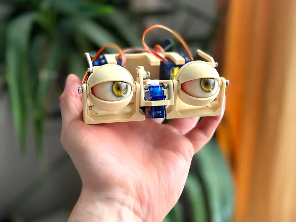
The intricate world of animatronics, a field that seamlessly blends mechanical engineering, electronics, and artistic design, continues to push the boundaries of realistic motion and expression. A recent detailed construction guide, published within the vibrant maker community, offers a comprehensive insight into the meticulous process of assembling advanced animatronic eyes. This project, which meticulously outlines the steps from fundamental structural assembly to the integration of delicate eyelid mechanisms, exemplifies the growing accessibility and sophistication of DIY robotics and animatronics, signaling a significant stride in personal fabrication and educational technology.
The construction of these animatronic eyes begins with establishing the foundational mechanical framework, crucial for ensuring precise and fluid movement. The initial phase involves the secure connection of two primary bases utilizing either 10mm or 12mm M3 bolts. This critical juncture is engineered to serve as the primary pivot point for the y-axis motion, governing the vertical movement of the eye assembly, including the synchronized actuation of the eyelids. The choice of M3 bolts, a standard in small-scale mechanical assembly, provides a robust yet compact connection, essential for the delicate balance required in animatronic mechanisms. This initial pivot sets the stage for the complex interplay of rotational and linear movements that will ultimately bring the artificial eyes to life, enabling them to convey a range of expressions and focus points.

Following the establishment of the y-axis pivot, attention shifts to integrating the primary actuator responsible for horizontal eye movement. A compact servo motor, specifically a TowerPro SG90 as implied by common usage in such projects, is precisely positioned and secured into its designated slot using 4mm or 6mm M2 screws. This servo acts as the primary driver for the x-axis motion, dictating the left-to-right gaze of the animatronic eyes. The selection of the SG90 servo, known for its small form factor, light weight, and sufficient torque for manipulating light loads, is characteristic of projects prioritizing efficiency and compact design. Its integration at this early stage underscores the project’s modular design, where distinct axes of motion are independently driven yet designed for synergistic operation. The precise placement and fastening of this servo are paramount, as any misalignment could introduce friction or impede the smooth range of motion, thereby compromising the realism of the eye movements.
With the core x-axis actuation in place, the next step involves attaching the y-axis arm to the sub-base. This connection is facilitated by a 4mm, 5mm, or 6mm M3 screw, ensuring a stable link between the vertical motion arm and the underlying structure. Simultaneously, a servo horn is attached to the third hole from the center of the y-axis arm, secured with a 4mm or 6mm M2 screw. The careful selection of the servo horn attachment point is a deliberate design choice, allowing for optimal leverage and translation of the servo’s rotational movement into the desired angular displacement of the y-axis arm. This stage requires a meticulous check of the orientation of all components to prevent any mechanical interference or incorrect movement patterns, which could lead to restricted motion or operational failure down the line. The alignment here directly influences the accuracy and naturalness of the vertical eye and eyelid movements.
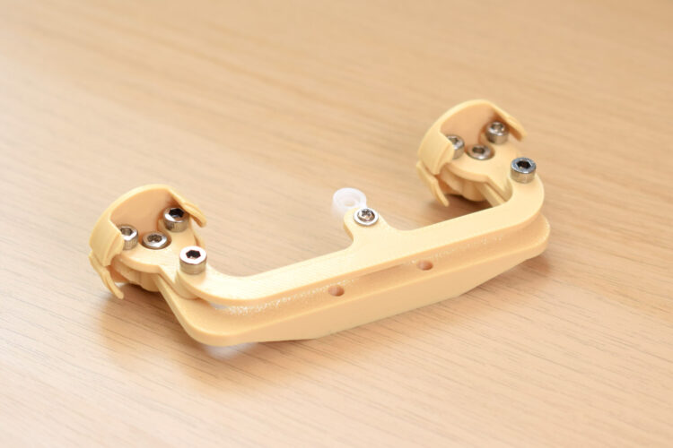
The construction then progresses to the x-axis assembly, a more intricate sub-system responsible for translating linear servo motion into the rotational movement of the eyes. This begins with screwing the "forks" into the "eye-adaptors" using 4mm, 5mm, or 6mm M3 bolts. A key design feature highlighted in this step is the intentional oversizing of the fork holes, allowing the screws to "bite" directly into the adaptor material. This method, often employed in 3D-printed assemblies, creates a secure, self-tapping connection without the need for additional nuts, simplifying assembly and reducing part count. The guide notes that one bolt may need to be inserted at an unconventional angle, suggesting a clever, compact design that maximizes space utilization within the limited confines of the eye mechanism. This assembly is critical as it forms the direct interface with the artificial eyes themselves, dictating their horizontal positioning.
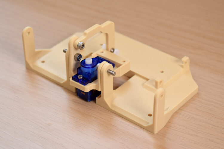
Further enhancing the x-axis assembly, a three-point connector is attached to the top of the forks. Here, an M3 screw engages with an undersized hole in the fork component, again utilizing the self-tapping principle for a firm connection. Concurrently, a servo arm is affixed to the final hole at the center of this three-point connector, secured by a 5mm M3 bolt. The guide advises that the servo arm’s hole may require pre-drilling to a size between 2.5mm and 2.8mm to properly accommodate the screw. This modification is common in hobbyist animatronics, where generic servo horns might need slight adjustments to fit specific project requirements, ensuring a precise and tight fit. Throughout this phase, regular manipulation of the assembly is recommended to verify smooth movement and identify any sources of friction. This iterative testing is vital in animatronic construction, where even minor impediments can significantly detract from the realism and fluidity of motion.
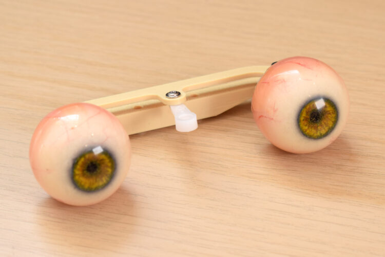
The penultimate step in assembling the core eye mechanism involves attaching the eye center-link to the eye adaptors. An 8mm M3 screw is used for this connection, with specific instructions to ensure the flat surface of the center-link faces upwards and its sloping section faces downwards. This orientation is crucial for the correct mechanical function and aesthetic positioning of the eyes. At this stage, the actual artificial eyes can be plugged into their adaptors, completing the optical component of the assembly. These "eyes" are typically spherical components, often pre-fabricated or 3D-printed, designed to mimic the appearance of real eyeballs and to interface seamlessly with the mechanical structure. Their integration marks a significant visual milestone in the construction process, as the animatronic mechanism begins to take on its intended form.
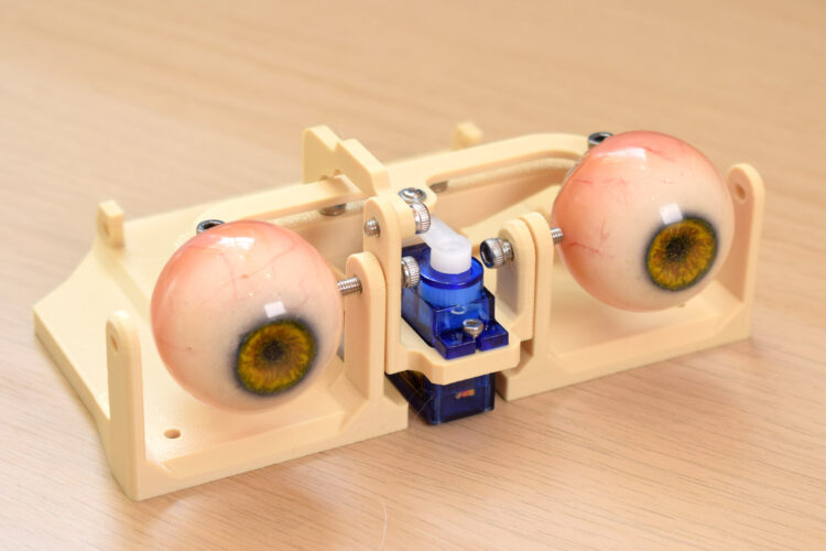
Finally, the entire assembled eye mechanism, including the eye center-link and adaptors, is securely fastened to the center of the sub-base using two 12mm M3 bolts. This step integrates the complete, articulated eye unit onto the main structural platform, ensuring it is stably mounted and ready for further integration with the servo control system. The choice of two bolts provides a secure, redundant attachment point, critical for preventing wobble or displacement during operation. This robust mounting ensures that the intricate movements of the eye assembly are consistently and reliably translated from the servos.
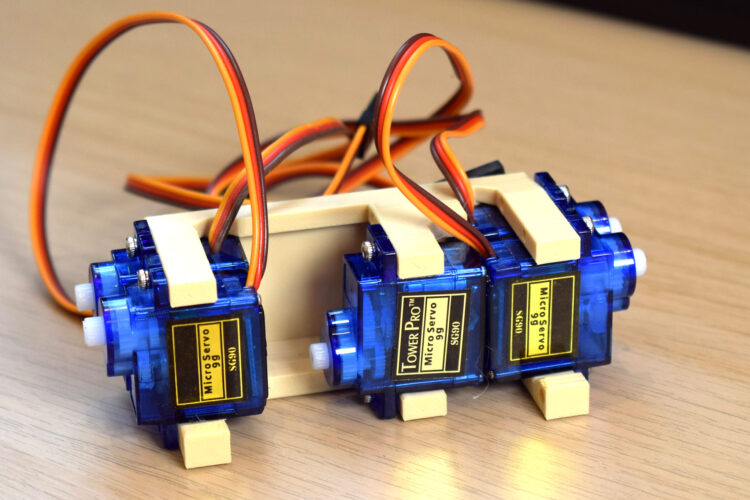
The project then moves to the broader integration of the servo control system. A dedicated "servo block" is loaded with five TowerPro SG90 servos, each carefully oriented according to the provided photographic guide. These additional servos are likely allocated for controlling the intricate movements of the eyelids and potentially other auxiliary facial movements, demonstrating the multi-axis capabilities of the animatronic design. Once populated, this servo block is attached to the main base using four M3x10mm bolts. The strategic placement of these five servos allows for independent control over various expressive elements, enabling a wide range of realistic blinks, glances, and subtle facial nuances. The use of multiple servos, each dedicated to a specific movement, underscores the complexity and fidelity achievable in modern animatronics, even at a DIY level.
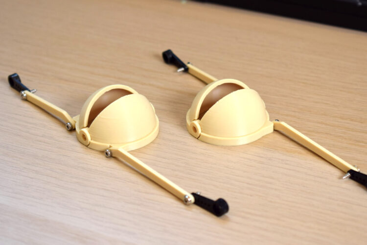
The concluding mechanical assembly step focuses on the eyelids, which are pivotal for conveying emotion and realism. The guide instructs builders to identify the correct eyelid components, which are then connected to their respective connectors using 4mm or 6mm M2 screws. Critically, a servo arm is attached to the other end of each eyelid connector, utilizing the last hole in the servo horn. Similar to previous steps, this hole may require pre-drilling to a smaller diameter, between 1.5mm and 1.8mm, to ensure a snug fit for the M2 screw. This precise connection ensures that the servo’s rotational input translates directly into the opening and closing motion of the eyelids. The final action in this sequence is to attach the assembled eyelids to the base, though without connecting them to the servo horns at this preliminary stage. This allows for initial positioning and alignment before the final calibration and electronic integration. The separation of mechanical attachment from servo linkage is a common practice, enabling adjustments and verification before committing to the final operational setup.
Technical Specifications and Component Analysis
The selection of components in this animatronic eye project reflects a thoughtful balance between performance, cost-effectiveness, and ease of assembly for the maker community. M3 and M2 bolts, ranging from 4mm to 12mm in length, are standard metric fasteners widely available and suitable for securing plastic components, often 3D-printed. Their varying lengths allow for secure fastening through different thicknesses of material, providing structural integrity. The use of self-tapping screws into undersized holes in 3D-printed parts is a common and efficient assembly technique, reducing the need for threaded inserts or nuts, which can add complexity and cost.
The reliance on TowerPro SG90 servos is particularly significant. These micro servos are ubiquitous in hobby robotics and electronics due to their low cost, small size (approximately 23x12x29mm), light weight (around 9 grams), and adequate torque (up to 1.8 kg-cm at 6V) for moving lightweight components like animatronic eyes and eyelids. Their operating voltage (typically 4.8V-6V) makes them compatible with common microcontroller platforms like Arduino or Raspberry Pi, further simplifying the electronic control aspect of the project. The project’s design leverages the SG90s’ capabilities to provide independent control over multiple degrees of freedom: horizontal eye movement (x-axis), vertical eye movement (y-axis), and individual eyelid control (upper and lower for each eye). This multi-servo approach allows for a high degree of expressive fidelity, crucial for realistic animatronic performance.
The mechanical components described—bases, sub-bases, y-axis arms, forks, eye-adaptors, three-point connectors, and eye center-links—are almost certainly custom-designed and 3D-printed. The mention of "oversized holes" for screws to "bite" into, and the need for drilling servo arm holes, strongly suggests the use of additive manufacturing. 3D printing allows for rapid prototyping and the creation of complex geometries tailored precisely to the functional requirements of the animatronic mechanism, making advanced projects accessible to individual makers with desktop 3D printers. The materials used would typically be PLA (Polylactic Acid) or ABS (Acrylonitrile Butadiene Styrene) for their printability and mechanical properties.
Broader Context and Implications in the Maker Community
This detailed assembly guide is more than just a set of instructions; it represents a significant contribution to the burgeoning field of DIY animatronics and the broader maker movement. Animatronics, historically a domain of large production studios for film, theme parks, and specialized industrial applications, has seen a democratizing shift in recent years. The availability of affordable microcontrollers, low-cost servos like the SG90, accessible 3D printing technology, and open-source design platforms has empowered individuals and small teams to create sophisticated robotic systems that were once beyond their reach.
The context of a publication like Makezine, which is known for fostering innovation and sharing practical projects, underscores the educational and inspirational value of such guides. These projects serve as vital learning tools, teaching fundamental principles of mechanical design, electronic control, and programming. For aspiring engineers, roboticists, and artists, building animatronic eyes provides a tangible, engaging way to understand kinematics, servo control, and the challenges of creating lifelike motion. The iterative nature of assembly, where troubleshooting friction and ensuring smooth operation are emphasized, cultivates critical problem-solving skills.
The implications extend beyond individual skill development. Accessible animatronics projects foster a culture of innovation. By lowering the barrier to entry, more individuals can experiment with human-robot interaction, explore expressive robotics for assistive technologies, or develop interactive art installations. The ability to create realistic eye movements is a cornerstone of believable animatronic characters, enhancing immersion in entertainment, educational exhibits, and even in fields like prosthetics, where naturalistic movements are paramount.
Furthermore, the detailed nature of the instructions, complete with specific bolt sizes and component orientations, speaks to the collaborative spirit of the maker community. Such guides enable reproducibility and allow others to build upon existing designs, accelerating collective learning and technological advancement. The visual aids, like the accompanying photographs, are indispensable, offering clear references that mitigate ambiguity in complex assembly steps. This level of documentation is crucial for scaling up hobbyist projects into more robust and widely adopted applications.
Conclusion: A Glimpse into the Future of Expressive Robotics
The meticulous assembly process for these animatronic eyes highlights the sophisticated engineering that underpins seemingly simple, lifelike movements. From the precise pivot points to the coordinated action of multiple micro-servos and the custom-fabricated components, each step is designed to contribute to a fluid and expressive robotic gaze. This project not only showcases the technical feasibility of advanced animatronics within a DIY framework but also underscores the profound impact of open-source knowledge sharing and accessible technology. As the capabilities of individual makers grow, the potential for animatronics to influence fields from entertainment to education and beyond continues to expand, promising a future where expressive, interactive robotic companions and tools become an increasingly common part of our technological landscape. The ability to craft such intricate systems at a personal level marks a significant step towards democratizing the art and science of robotics, inspiring a new generation of innovators to animate their imaginations.