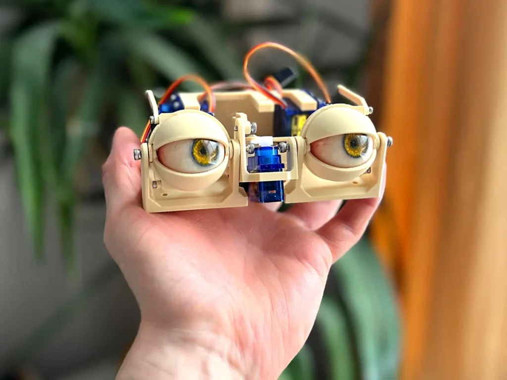
The intricate world of animatronics continues to push the boundaries of realism, and at its heart lies the meticulous engineering of expressive features. Among these, the eyes hold paramount importance, serving as the primary conduit for conveying emotion and lifelike presence. A recent detailed assembly guide, featured on Makezine.com and documented through the expert photography of Will Cogley, sheds light on the precise construction of sophisticated animatronic eyes, detailing the mechanical and electronic synergy required to achieve compelling, articulated movement. This project highlights the growing accessibility of advanced robotics for hobbyists and professionals alike, offering a blueprint for creating nuanced eye and eyelid motions that are critical for believable character animation in various applications.
The Foundational Structure: Establishing the Dual-Axis Movement

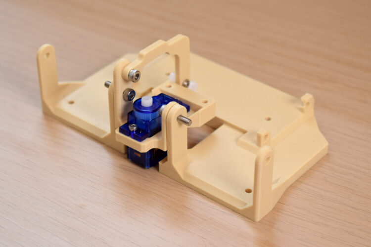
The journey to creating animatronic eyes capable of conveying a spectrum of expressions begins with the establishment of a robust and precisely engineered mechanical foundation. The initial phase focuses on assembling the core pivot points that will govern both vertical (y-axis) eye movement and the synchronized motion of the eyelids. This critical first step involves connecting two primary bases using 10mm or 12mm M3 bolts. These particular bolt dimensions are selected for their optimal balance of strength and compact size, ensuring a secure yet fluid connection. The joint formed by these bolts is designated as the primary pivot point for the y-axis, allowing the entire eye assembly to tilt up and down, mimicking natural human eye movement. Crucially, this same pivot also serves as the anchor for the eyelid mechanisms, enabling their coordinated action with the eye’s vertical orientation.
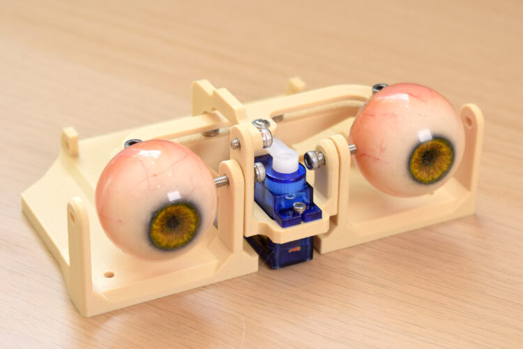
Immediately following the establishment of the y-axis pivot, attention shifts to integrating the primary actuator for horizontal movement. A compact servo motor, an essential component in modern animatronics for its precise rotational control, is carefully placed into its designated position within the structure. This servo, often a micro-servo model known for its power-to-size ratio, is then secured using 4mm or 6mm M2 screws. The choice of M2 screws, smaller in diameter than M3, reflects the need for fine-tuned attachment of smaller electronic components, preventing over-tightening or damage to the servo casing. This servo is strategically positioned to serve as the actuator for the x-axis motion, enabling the animatronic eyes to look left and right. The combined functionality of the y-axis pivot and the x-axis servo forms the bedrock of the system, providing the fundamental degrees of freedom required for dynamic eye movement.
Precision Linkages: Connecting Actuators to Eye Movement
With the foundational pivots and primary x-axis actuator in place, the next series of steps involves constructing the intricate linkages that translate servo rotation into the desired eye movements. The y-axis arm, a crucial component for vertical motion, is meticulously attached to the sub-base. This attachment is achieved using an M3 screw, with lengths typically ranging from 4mm to 6mm, depending on the specific design and material thickness. The selection of an M3 screw ensures a strong, stable connection that can withstand the repetitive motions of the y-axis.
Following the arm’s attachment, a servo horn – a small, multi-holed disk that transfers the servo’s rotational force to mechanical linkages – is secured to the y-axis arm. This is attached to the third hole from the center of the horn, using a 4mm or 6mm M2 screw. The specific hole choice on the servo horn is critical, as it determines the leverage and range of motion for the y-axis, allowing for fine-tuning of the eye’s vertical travel. During this stage, a vital checkpoint is emphasized: verifying the correct orientation of all components. Any misalignment or incorrect placement can lead to friction, limited movement, or even mechanical failure, underscoring the importance of precision in animatronic assembly.
The construction then progresses to the x-axis assembly, which demands a similar level of meticulousness. This phase begins with screwing the "forks" into the "eye-adaptors" using 4mm, 5mm, or 6mm M3 bolts. The design ingeniously incorporates oversized holes in the fork components, allowing the M3 screws to "bite" directly into the material of the adaptor, creating a self-tapping effect that ensures a very secure, custom fit. This method is particularly useful in 3D-printed or custom-machined parts where threaded inserts might be impractical. Acknowledging a common challenge, the guide notes that one of these bolts might need to be inserted at a "funny angle," a testament to the compact and often complex geometries involved in animatronic design, yet assuring builders that it can be successfully secured.
Advanced Articulation: Coordinating Eye and Eyelid Motions
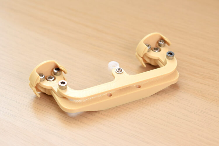
The complexity of the animatronic eye mechanism deepens with the integration of multi-point connectors and further servo linkages to achieve highly coordinated movements. The three-point connector, a key element in distributing force and motion, is attached to the top of the previously assembled forks. Here, an M3 screw is used, designed to bite into an undersized hole within the connector component, ensuring a tight, reliable fit without play. Simultaneously, another servo arm is affixed to the final hole at the center of this three-point connector. This attachment utilizes a 5mm M3 bolt, though it often necessitates drilling the servo arm’s hole to a slightly larger diameter (typically 2.5mm to 2.8mm) to accommodate the screw snugly. The repeated emphasis on manipulating the assembly throughout these steps — checking for smooth movement and absence of friction — highlights the iterative nature of animatronic construction, where small adjustments during assembly prevent larger issues later.
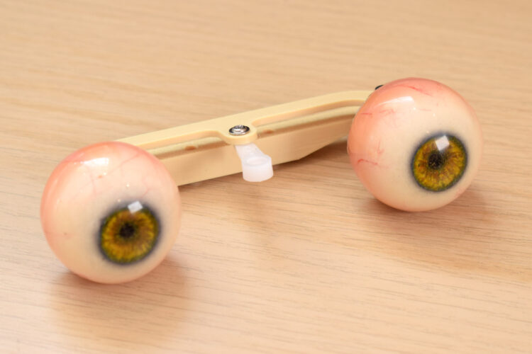
Following the articulation of the x-axis, the "eye center-link" is introduced, serving to synchronize the movements of the individual eye adaptors. This component is attached to the eye adaptors using an 8mm M3 screw. Crucially, the guide specifies the correct orientation: the flat surface of the center-link must face upwards, while the sloping section faces downwards. This seemingly minor detail is critical for ensuring the correct kinematic movement and preventing mechanical interference. At this juncture, the actual animatronic "eyes" — often pre-fabricated spheres with printed irises and pupils — are plugged into their respective adaptors, bringing the system closer to its visual completion. The entire sophisticated assembly, comprising the x-axis mechanism, eye adaptors, and center-link, is then securely fastened to the center of the sub-base using two 12mm M3 bolts, providing a stable platform for all subsequent operations.
The Eyelid System: Achieving Expressive Blinks and Gazes
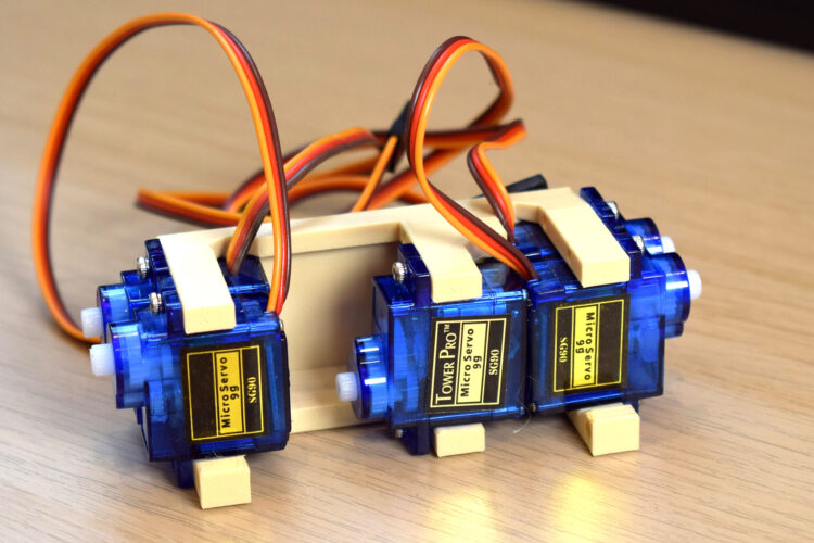
A truly lifelike animatronic eye requires more than just directional movement; it demands expressive eyelids. This project employs a dedicated servo block to manage these nuanced motions. The servo block is loaded with five TowerPro SG90 servos, a popular choice in the hobbyist and maker community due to their affordability, compact size, and sufficient torque for small-scale applications. The correct orientation of each servo within the block is critical, as it dictates the direction of movement for the eyelids and other potential facial features. Once all five servos are precisely positioned, the entire servo block is robustly attached to the main base using four M3x10mm bolts, ensuring a firm and stable mounting that can endure continuous operation.
The articulation of the eyelids themselves is then addressed. Builders are guided to identify the specific upper and lower eyelids using visual references, often provided in accompanying photographs. Each eyelid is then connected to its relevant connector using a 4mm or 6mm M2 screw. A dedicated servo arm is attached to the other end of this connector, typically utilizing the outermost hole in the servo horn. Similar to previous steps, this often requires a small modification, specifically drilling the servo horn hole to a diameter between 1.5mm and 1.8mm to precisely fit the screw. These individual servo-to-eyelid linkages allow for independent control of each eyelid, enabling a wide range of expressions, from subtle blinks to more pronounced winks or squints, greatly enhancing the animatronic character’s emotional depth. Finally, the eyelids are attached to the base structure, though the guide advises against connecting the servo horns to the servo output shafts at this stage. This allows for initial mechanical positioning and ensures that the servos can be zeroed or calibrated before their horns are permanently attached, a best practice in animatronic and robotics assembly to prevent damage and ensure accurate movement ranges.
Broader Context and Implications: The Rise of Accessible Animatronics
This detailed assembly guide for animatronic eyes, as presented on platforms like Makezine.com, represents more than just a set of instructions; it signifies a significant trend in the democratization of advanced robotics and special effects technology. Historically, animatronics were the exclusive domain of large film studios, theme parks, and highly specialized engineering firms. However, with the advent of affordable microcontrollers, reliable miniature servo motors like the TowerPro SG90, accessible 3D printing, and open-source design communities, the barrier to entry for creating complex mechanical systems has dramatically lowered.
The meticulous detail in bolt sizes (M2, M3), lengths (4mm to 12mm), and specific drilling requirements (2.5mm-2.8mm for servo arms, 1.5mm-1.8mm for eyelid horns) underscores the precision engineering now achievable by hobbyists. These components, readily available from electronics suppliers worldwide, offer a standardized yet flexible toolkit for makers. The strategic use of oversized holes for screw "biting" into material, as seen in the fork-to-adaptor connection, exemplifies innovative problem-solving that leverages the properties of common materials and fasteners. The design’s consideration for smooth movement and friction prevention, emphasized throughout the building process, reflects fundamental principles of mechanical design crucial for long-term functionality and realism.
The implications of such accessible projects are far-reaching. In education, these types of builds provide invaluable hands-on STEM learning experiences, teaching students about mechanical linkages, electronic control, and the physics of motion in an engaging way. For the burgeoning maker community, these guides foster skill development, collaboration, and innovation, empowering individuals to bring their creative visions to life. From independent filmmakers and cosplay enthusiasts seeking to elevate their creations to researchers exploring human-robot interaction and expressive artificial intelligence, the ability to construct realistic animatronic features is a game-changer.
Furthermore, the continuous pursuit of lifelike movement in animatronics directly addresses the "uncanny valley" phenomenon – the unsettling feeling observers experience when robots or artificial figures appear almost, but not quite, human. Projects that meticulously detail the mechanics of eye and eyelid movement are crucial steps in bridging this gap, allowing animatronic characters to convey genuine emotion and presence. The ability to control not just the direction of gaze but also the subtle nuances of blinks, squints, and lid articulation adds layers of realism that are essential for believable character performance.
The future trajectory of animatronics, propelled by such accessible and detailed guides, points towards increasingly sophisticated and personalized creations. As component costs continue to decrease and design tools become more intuitive, we can anticipate a proliferation of animatronic projects that push the boundaries of expressive realism, ultimately enriching fields from entertainment and education to therapeutic robotics and beyond. This specific guide for animatronic eyes stands as a testament to the ingenuity of the maker community and the profound impact of shared knowledge in advancing technological artistry.