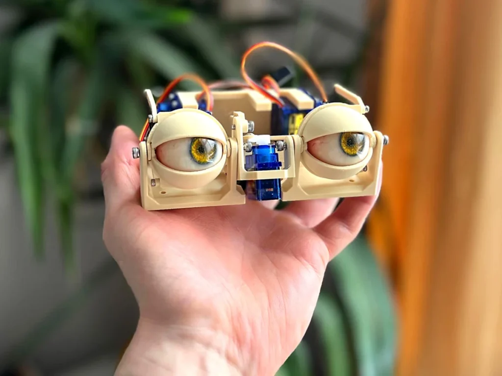
The intricate assembly of animatronic eyes represents a crucial frontier in robotics and immersive entertainment, where precise mechanical engineering translates into lifelike expressions. This detailed construction guide outlines the sophisticated process of building a multi-axis eye movement and eyelid system, highlighting the meticulous integration of various components to achieve fluid, realistic motion. The project emphasizes the delicate balance between structural integrity and dynamic articulation, a cornerstone for creating believable robotic characters.
The Foundation of Movement: Establishing the Y-Axis Pivot

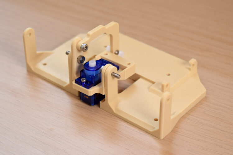
The initial phase of constructing an animatronic eye mechanism centers on establishing the primary vertical axis of motion, often referred to as the y-axis. This pivot point is fundamental for both the upward and downward gaze of the eye and the synchronized movement of the eyelids. Engineers begin by connecting two critical base components using either 10mm or 12mm M3 bolts. The choice of M3 bolts, a standard in small-scale mechanical assemblies, ensures a robust connection while providing sufficient clearance for rotational movement. The specific length of the bolt is critical; a 10mm bolt offers a snug fit for thinner materials, while a 12mm bolt accommodates slightly thicker components or allows for the inclusion of washers to reduce friction and maintain a consistent pivot. This carefully engineered pivot is designed to minimize play, ensuring that the vertical motion of the eyes and eyelids is smooth and predictable, a prerequisite for conveying subtle emotional cues. The precision in this initial step sets the stage for the entire system’s performance, as any looseness or misalignment here would propagate through subsequent movements, compromising the realism of the animatronic gaze.
Actuating Horizontal Gaze: The X-Axis Servo Integration
Following the establishment of the y-axis, the focus shifts to integrating the mechanism responsible for horizontal eye movement, or the x-axis. This is typically achieved through the strategic placement of a micro servo motor, a compact yet powerful actuator widely favored in hobbyist robotics and animatronics for its precise angular control. The servo is carefully positioned within the assembly and secured using 4mm or 6mm M2 screws. The smaller M2 screws are ideal for securing components where space is at a premium and high torque is not applied directly to the screw heads, providing a firm attachment without risking overtightening or stripping the threads in plastic components. This servo serves as the primary actuator for the x-axis motion, directly translating electrical signals into rotational movement that, through a series of linkages, will guide the eyes left and right. The precise mounting of this servo is paramount; its alignment dictates the accuracy and range of the horizontal eye sweep. Improper mounting can lead to skewed movement, increased friction, or even mechanical binding, all of which detract from the naturalness of the animatronic’s gaze.
Synchronizing Vertical Eye and Eyelid Motion
With the fundamental axes established, the next step involves connecting the y-axis arm to a sub-base. This connection is typically made with a 4mm, 5mm, or 6mm M3 screw, allowing for a robust yet flexible joint. The varying screw lengths provide options depending on the thickness of the sub-base and the desired depth of thread engagement. Crucially, a servo horn is then attached to this arm, specifically on the third hole from its center, utilizing a 4mm or 6mm M2 screw. The strategic placement of the servo horn, offset from the center, creates a lever arm that amplifies the servo’s rotational movement into a larger arc for the y-axis arm. This design allows for a greater range of vertical motion for the eyes and eyelids with relatively small servo inputs. Before proceeding, a thorough check of the orientation of all components is essential. This verification ensures that the servo horn, arm, and sub-base are correctly aligned, preventing mechanical conflicts and ensuring the intended range of motion. Any misorientation at this stage could lead to limited movement, excessive strain on the servo, or an unnatural appearance of the animatronic’s eye movements.
Constructing the X-Axis Assembly: Forks and Eye-Adaptors
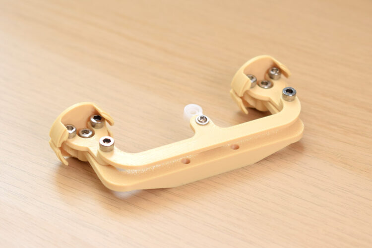
The horizontal eye movement system, the x-axis assembly, requires a more complex arrangement of components to translate the servo’s rotation into the precise lateral motion of the eyes. This assembly begins with screwing the forks into the eye-adaptors using 4mm, 5mm, or 6mm M3 bolts. A notable design feature here is that the fork holes are often intentionally oversized. This allows the M3 screws to "bite" directly into the material of the adaptor, creating a secure, self-tapping connection, especially common in 3D-printed or laser-cut plastic parts. While this method can occasionally result in a screw going in at a "funny angle" – a common challenge in DIY fabrication where tolerances might vary slightly – the design typically allows for sufficient engagement to form a strong bond. The forks themselves are critical linkages, designed to hold the eye components and translate the motion from the central actuator. The eye-adaptors are the interfaces that directly connect to the spherical "eyes" of the animatronic, ensuring they are held securely while allowing for smooth rotational movement. This iterative assembly process, where components are joined with careful attention to how screws interact with material, is characteristic of advanced maker projects.
Linking the Movement: Three-Point Connector and Servo Arm
Further integrating the x-axis assembly, a three-point connector is attached to the top of the forks. This component acts as a central hub, distributing motion and ensuring coordinated movement between the two eye units. Similar to previous steps, the M3 screw used here is designed to bite into an undersized hole within the fork component, ensuring a tight, secure fit. Crucially, a servo arm is then attached to the final hole at the center of this three-point connector, utilizing a 5mm M3 bolt. This connection point is vital as it directly links the entire x-axis eye assembly to the controlling servo. It is often necessary to drill the hole on the servo arm to a slightly larger diameter, typically between 2.5mm and 2.8mm, to perfectly accommodate the M3 screw. This minor modification highlights the practical adjustments often required in custom robotics to ensure optimal fit and function. Throughout this intricate assembly, it is strongly recommended to manipulate the mechanism regularly. By manually moving the components, builders can check for any friction points, binding, or unintended resistance. Identifying and rectifying these issues early ensures that the final animatronic eye movement will be fluid, natural, and free from mechanical hitches.
Integrating the Eye Units and Securing the Core Assembly
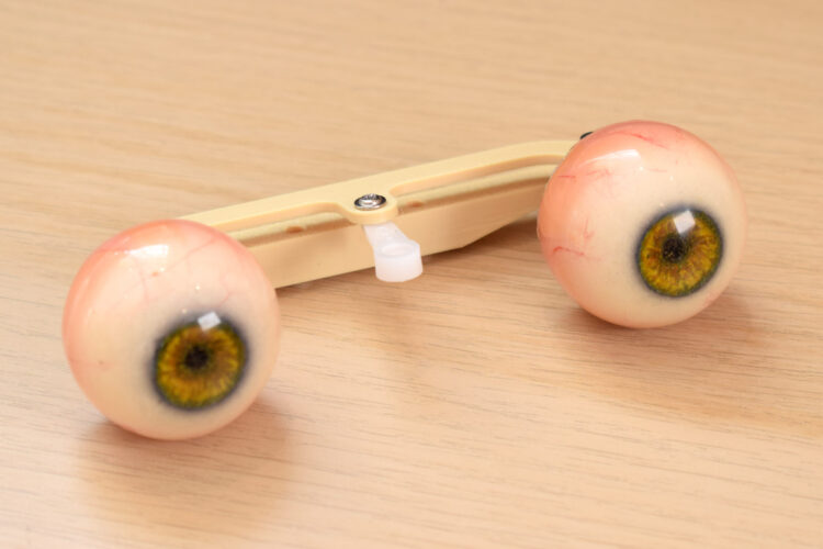
The next phase involves the physical integration of the animatronic eyes themselves and the consolidation of the x-axis movement mechanism. The eye center-link, a critical component that bridges the two eye adaptors, is attached using an 8mm M3 screw. The orientation of this piece is paramount: its flat surface must face upwards, while the sloping section faces downwards. This specific orientation is not merely aesthetic; it ensures proper clearance, prevents interference with other moving parts, and contributes to the overall structural integrity and desired range of motion for the eyes. Once the center-link is secured, the animatronic eye units can be plugged into their respective adaptors. These eye units, which could be anything from simple painted spheres to complex LED matrix displays, are now ready to receive motion inputs. With the individual eye units and their connecting linkage in place, the entire x-axis assembly – comprising the forks, eye-adaptors, three-point connector, and center-link – is then screwed to the center of the sub-base using two 12mm M3 bolts. These longer bolts provide ample thread engagement, securely anchoring the dynamic eye movement system to the stationary sub-base, establishing a robust and stable foundation for the complex motions to follow.
The Eyelid Actuation System: A Separate Layer of Expression
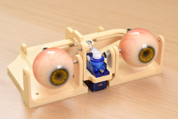
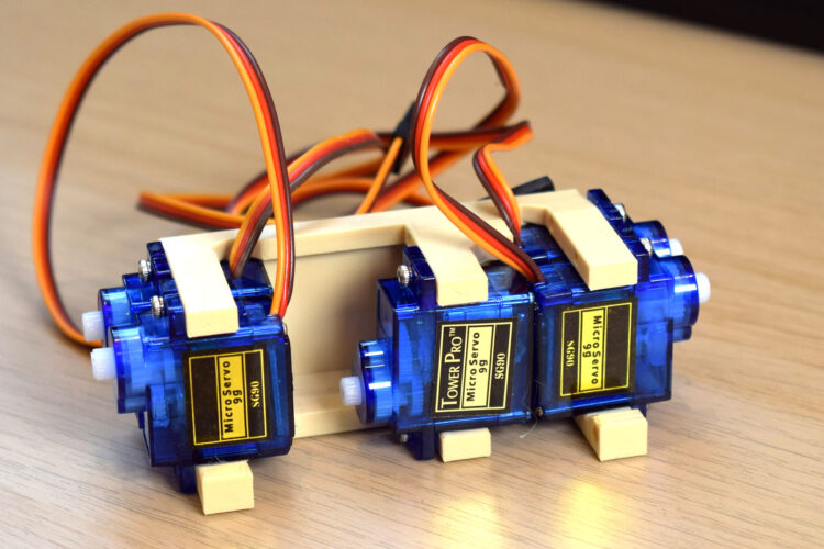
To achieve truly lifelike animatronic expressions, the eyelids require their own dedicated actuation system, distinct from the main eye movement. This is typically managed by a separate servo block, which is loaded with five TowerPro SG90 servos. The TowerPro SG90 is a popular choice among hobbyists and professional makers alike due to its compact size, light weight, and sufficient torque for small-scale applications like eyelid control, all at a cost-effective price point. The precise orientation of each servo within the block is critical, as incorrect placement could lead to inverse movements or mechanical interference. Once the servos are correctly loaded, the entire servo block is attached to the main base using four M3x10mm bolts. This secure mounting ensures that the eyelid servos remain stable during operation, providing consistent and reliable movement. The use of multiple servos allows for individual control over upper and lower eyelids, and potentially even subtle brow movements, significantly enhancing the range and nuance of emotional expression the animatronic can convey. This multi-servo approach moves beyond simple open/close eyelid functions, enabling blinks, winks, and nuanced squints that greatly contribute to the overall realism.
Connecting the Eyelids: Precision and Customization
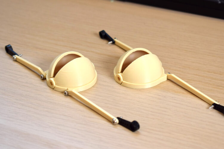
The final stage of mechanical assembly focuses on integrating the eyelids with their dedicated servo actuators. The process begins by carefully identifying which eyelid component corresponds to which position, often guided by photographic references provided by the designer. Each relevant connector for the eyelids is then attached with a 4mm or 6mm M2 screw, ensuring a firm but flexible joint. Subsequently, a servo arm is attached to the other end of this connector, utilizing the last hole in the servo horn. This choice of hole provides the maximum lever arm, allowing for the greatest range of motion for the eyelids from the servo’s rotation. A common requirement at this stage is the need to drill the servo horn hole to a smaller diameter, typically between 1.5mm and 1.8mm. This customization is necessary to ensure that the M2 screw used for the eyelid linkage creates a tight, secure fit without any wobble, which is paramount for smooth and precise eyelid movements. Finally, the eyelids themselves are attached to the base structure. However, it is explicitly noted that the servo horns should not be connected to the servos at this point. This deliberate deferral allows for a crucial calibration step later, where the servos can be powered on, centered, and then connected to the eyelids in their neutral position, ensuring correct starting points and preventing potential damage from misaligned initial connections. This methodical approach ensures that the delicate eyelid mechanisms are integrated with both structural integrity and functional precision.
The Broader Implications of Expressive Animatronics
The construction of such sophisticated animatronic eye systems holds significant implications across various fields, extending far beyond mere entertainment. In the realm of robotics, particularly in human-robot interaction (HRI), the ability of a robot to convey emotion and intent through realistic eye movements is transformative. Robots with expressive eyes can appear more approachable, trustworthy, and empathetic, fostering more natural and intuitive interactions with humans. This is crucial for applications in healthcare (companion robots), education (interactive tutors), and service industries (customer-facing robots).
From an educational perspective, projects like this serve as invaluable learning tools. They combine principles of mechanical engineering, electronics, and basic programming into a tangible, engaging experience. Students and hobbyists gain hands-on experience with servo motors, linkage mechanisms, and precision assembly, developing critical problem-solving skills and an understanding of how complex systems are built from simpler components. The challenges encountered, such as oversized holes or the need for drilling, teach practical fabrication techniques and the importance of adapting designs in real-world scenarios.
Historically, animatronics have captivated audiences, from the pioneering works of Walt Disney Imagineering to the blockbuster visual effects in cinema. The evolution from large, hydraulic-powered figures to compact, servo-driven mechanisms like the one described signifies a democratization of this technology. The increasing availability of affordable microcontrollers (like Arduino or Raspberry Pi), readily available components (such as TowerPro SG90 servos), and accessible manufacturing methods (like 3D printing) has empowered a global community of makers. This has led to an explosion of innovation in custom animatronics, enabling individuals to create characters for independent films, theatrical productions, escape rooms, or even personalized interactive art installations.
The precise control over eye gaze, combined with nuanced eyelid movements, allows for the simulation of a vast spectrum of emotions—from surprise and curiosity to sadness and anger. This level of expressive capability is not just for theatrical flair; it’s a vital component in creating truly believable artificial entities. As artificial intelligence continues to advance, providing robots with sophisticated cognitive abilities, the need for equally sophisticated physical expressions will only grow. Animatronic eyes are not just a mechanical marvel; they are a window into the potential for robots to connect with humans on a deeper, more emotional level, bridging the gap between machine and sentient-like presence. The ongoing refinement of these systems paves the way for a future where robotic companions and characters are not just functional, but also genuinely engaging and emotionally resonant.