In a world increasingly reliant on automation, understanding the fundamental principles of motion system design is paramount. This primer delves into the essential elements that constitute an automated motion system, whether it forms the backbone of sophisticated robotics or a machine dedicated to a specific routine. At its core, every motion system is an electric-motor-driven design built around two fundamental categories of components: the mechanical elements that translate motion and the electrical/electronic components that control and power it.
The Foundational Components of Motion Systems
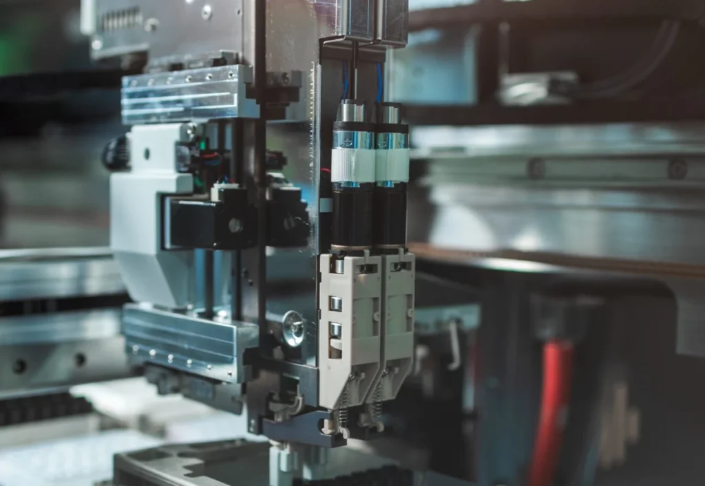
Motion systems, regardless of their complexity, are engineered assemblies where electric motors serve as the primary movers. These systems integrate two main types of components to achieve their operational goals. Firstly, there are the mechanical components, which include the physical structures and mechanisms that facilitate movement. This encompasses elements like linear actuators (screw-driven, belt-driven), rotary components (gearboxes, pulleys, chains, sprockets), linear guides, bearings, and the structural frame of the machine itself. These components are responsible for transmitting power, converting rotational motion into linear motion, and guiding the movement of loads. For instance, an advanced vision system scanning vials for defects, as commonly seen in pharmaceutical or quality control applications, typically incorporates electric motors paired with screw-driven and belt-driven linear axes, relying on precision linear guides for accurate horizontal movement.
Secondly, electrical and electronic components form the intelligent core, encompassing the electric motors themselves, motor drives (amplifiers), motion controllers, sensors, encoders, and the necessary wiring and communication infrastructure. These elements are tasked with generating power, interpreting commands, monitoring system performance, and ensuring precise, controlled execution of motion. The synergy between these mechanical and electrical components defines the system’s capabilities, dictating its speed, accuracy, force, and overall performance envelope.
Power Transmission vs. Precision Motion: Defining the Industrial Landscape
Within the industrial automation sector, a critical distinction is often made between "power-transmission designs" and "motion systems," reflecting different emphases in machine construction and application.
Power-transmission designs typically refer to machine builds where the primary focus is on delivering raw torque or force and achieving specific speeds. In these systems, mechanical components often dominate the design, engineered for robustness and the efficient transfer of power. Examples include conveyor belts moving heavy loads, large industrial mixers, or certain types of presses where the objective is to apply significant force or maintain a continuous, high-speed operation, often with less emphasis on intricate positioning accuracy.
In contrast, motion systems are characterized by their emphasis on precise positioning and controlled motion profiles. These systems meticulously define the speeds, accelerations, jerk (the rate of change of acceleration), speed-torque profiles, and homing routines for a machine’s various axes. Applications demanding high accuracy, repeatability, and dynamic control, such as robotic arms, CNC machines, or sophisticated packaging equipment, fall squarely into the motion system category. The integration of advanced controls and feedback mechanisms is crucial here to ensure the machine executes complex, multi-axis movements with minimal deviation from the desired trajectory. The global motion control market, valued at approximately $15 billion in 2023, is projected to grow steadily, underscoring the increasing demand for precision and automation across industries.

Both design philosophies are integral to a vast array of modern products and processes. They are the hidden engines behind myriad consumer products, office automation equipment, medical devices, and laboratory automation equipment. In the industrial sphere, they are the cornerstone of discrete factory automation, a sector that stands in contrast to process or analog automation.
Discrete vs. Process Automation: A Fundamental Divide
The industrial landscape is broadly categorized into two primary forms of automation: discrete and process. Understanding this distinction is vital for appreciating where motion system designs truly shine.
Discrete automation involves the working, machining, assembling, testing, capping, wrapping, packaging, labeling, counting, scanning, and transporting of separate, individual products or workpieces. Each item often undergoes several distinct operations before completion. This type of automation is characterized by distinct starts and stops, individual unit handling, and often, complex sequences of movements. Industries where discrete automation is prevalent include automotive manufacturing, electronics production, automated warehousing and logistics operations, and packaging. For instance, an assembly line for smartphones involves precise robotic arms placing tiny components, conveyor systems transporting individual units, and vision systems inspecting each device for defects—all requiring highly coordinated motion control.
Conversely, process automation deals with continuous flows, batches, or vats of liquids, gases, or other bulk materials. It focuses on uninterrupted systems of fluids, continuous chemical reactions, temperature controls, metering, and flowing operations that are generally difficult to stop and start. Process automation industries, where these types of operations dominate, include mining, energy (coal, nuclear, renewables), oil and gas, large-scale food processing (e.g., brewing, dairy), pharmaceutical and chemical manufacturing, glass and ceramic production, plastics, textiles, and wood and paper. Here, the emphasis is on maintaining steady states, regulating flow rates, and controlling environmental parameters, often using valves, pumps, and continuous sensors, rather than precise positional movements of individual items.
Motion system designs are predominantly associated with discrete automation. Their inherent capability to deliver precise placement, controlled movement, and synchronized transport of discrete workpieces or individual products makes them indispensable for the efficient and high-quality production demanded by modern manufacturing.
Parameters Pertinent to the Motion System Design Process: A Chronological Approach
The design of an automated motion system is a methodical process that begins with a thorough understanding of the physical demands placed upon the system.
1. Quantifying Loads, Inertias, and Friction:
The initial phase of any motion design involves meticulously documenting the loads that need to be moved and the inertias involved. Inertia, defined as an object’s resistance to changes in speed (acceleration or deceleration), is a critical parameter. The total inertia includes not only that of the workpiece but also the moving parts of the axes themselves. This value can range significantly: from very low in direct-drive or linear motors (which have no intermediate mechanical components) to considerably higher when an electric motor is fitted with a gearset for speed reduction or for inertia matching in servotuning.

Inertial values also vary for axes incorporating different power transmission mechanisms. Tangential forms of power transmission, such as belt-and-pulley, rack-and-pinion, or chain-and-sprocket sets, each contribute distinct inertial characteristics. Similarly, linear actuators employing leadscrews, ballscrews, or roller screws will have different inertial profiles. Engineers must sum all axis components’ inertias and calculate what is "reflected back" to the axis’s motor-output shaft. This calculation is vital for ensuring the motor can effectively manage the system’s dynamics. A unique challenge arises in designs with changing inertia, such as robotic axes performing dispensing or machining tasks where the mass of the end-effector changes during operation. In such cases, the motion controls may require adaptive servotuning to compensate for these dynamic shifts, a complex task that underscores the need for robust control algorithms.
2. Defining Required Motor Output Force and Torque:
Once the mechanisms are defined, and their friction and inertia quantified, the next crucial step is to determine the required motor output force (for linear motors) or, more commonly, torque (for rotary motors). This allows for the proper sizing of the electric motor for each axis. The motor must deliver sufficient acceleration torque to overcome inertia and friction, maintain constant torque during run phases, and provide deceleration torque for controlled stopping. This involves analyzing the complete duty cycle of the motion profile, ensuring that the selected motor can handle peak torque demands during acceleration and deceleration, as well as continuous torque requirements without overheating. Over-sizing can lead to unnecessary cost and energy consumption, while under-sizing can result in performance failures or premature motor wear.
3. Motor and Motion Control System Selection:
The past two decades have witnessed a significant convergence of motor control and motion control technologies. Both types of electronics accept low-power signals and translate them into actuation-level electrical output to drive motors. In essence, motion controllers act as the "brains" of the system, monitoring, commanding, and integrating various components. They manage:
- Trajectory generation: Calculating the desired path and speed.
- Position and velocity control: Ensuring the motor follows the commanded trajectory.
- Synchronization: Coordinating multiple axes for complex movements.
- Error compensation: Adjusting for deviations between commanded and actual motion.
Motion controllers can be arranged for:
- Point-to-point positioning: Moving an axis from one specific location to another.
- Path interpolation: Smoothly moving along a defined curve or line.
- Gearing or camming: Synchronizing the motion of one axis to another.
A key design decision involves choosing between centralized controls (where controls, motors, drives, and complementary electronics are housed together in a single cabinet) and distributed drive-based controls. Machines with numerous axes spread over a large area often benefit from decentralized motion control, which can significantly reduce wiring complexity and costs, leading to smaller control cabinets and simpler installation. Conversely, compact machine installations may find centralized control more economical due to its inherent simplicity and lower initial hardware cost. Industry trends, driven by the Industrial Internet of Things (IIoT) and Industry 4.0, increasingly favor distributed intelligence and edge computing, pushing control closer to the actuators for faster response times and greater modularity.
Regardless of the chosen architecture, each motor’s drive (motor control or amplifier) must be capable of providing sufficient acceleration and continuous current to satisfy the motion design’s duty-cycle requirements. This includes the power needed to move the load and dissipate heat during both acceleration and deceleration, ultimately dependent on the RMS (root mean square) current or acceleration current, while accounting for any increase in the motor’s winding resistance due to heat generation.
The Special Case of Servosystems
Motion system designs configured as closed-loop systems, known as servosystems, are dynamic machines engineered for quick accelerations and decelerations and capable of operation in all four design quadrants (controlling an axis across positive and negative torques and speeds). Sizing such servosystems demands a holistic, systems-level approach that concurrently considers mechanical, electrical, and software parameters. The drives supplying power to a servomotor must be capable of delivering all necessary continuous (RMS) and acceleration (peak) currents to ensure robust and responsive performance. Servosystems are widely adopted in applications requiring high precision, speed, and dynamic control, such as industrial robots, CNC machines, and high-speed packaging lines, where even minor deviations can lead to significant quality issues or production losses.
Motion System Design Environmental Considerations

The operational environment profoundly impacts component selection for a motion system. Where a motion design is destined for hot, dusty, washdown, vacuum, explosive, or other challenging industrial environments, the power-transmission, electromechanical, and electronic components must be chosen for their ruggedness and specific protective ratings.
- IP Ratings (Ingress Protection): These ratings, defined by international standards (IEC 60529), indicate a component’s resistance to solids (dust, dirt) and liquids (water). For example, IP67 signifies total protection against dust and temporary immersion in water.
- NEMA Ratings (National Electrical Manufacturers Association): Primarily used in North America, NEMA ratings provide similar protection levels, often with additional considerations for corrosion, hazardous locations, and icing.
- Washdown Environments: Components for food and beverage processing or pharmaceutical applications require stainless steel construction, smooth surfaces to prevent microbial growth, and high IP ratings to withstand frequent high-pressure washdowns with detergents.
- Cleanroom Environments: In industries like semiconductor manufacturing or medical device assembly, components must meet strict cleanroom classifications (e.g., ISO Class 1 to 9), minimizing particulate generation and outgassing. Special lubricants, enclosed designs, and low-friction materials are often required.
- Explosive Environments: Components for oil and gas, chemical plants, or grain handling must be rated for hazardous locations (e.g., ATEX or IECEx certifications) to prevent ignition of flammable gases or dust. This often involves explosion-proof enclosures or intrinsically safe designs.
These ratings and features are crucial for ensuring the reliability, longevity, and safety of motion systems operating under adverse conditions, preventing costly downtime and regulatory non-compliance.
Feedback, Connectivity, and Communication Protocols for Motion Designs
Many motion system designs depend heavily on sensors and encoders to accurately track position, velocity, and other critical axis values during machine operation. These feedback devices are the "eyes and ears" of the motion controller, providing the necessary data for closed-loop control.
- Hall-effect sensors: Used for basic position detection, often in commutation of brushless DC motors.
- Resolvers: Robust analog devices providing absolute position feedback, suitable for harsh environments.
- Encoders:
- Incremental encoders: Generate pulses as they move, providing relative position and velocity information. Require a homing routine to establish an absolute zero.
- Absolute encoders: Provide unique position data for each shaft angle, maintaining position even after power loss.
- Other feedback devices: Various forms of mechanical switches, optical sensors, and magnetic feedback devices are employed depending on the specific application requirements.
These devices convert their collected signals into (often digital) data for the motion controls to use in trajectory calculations and error corrections. The choice of feedback device is intrinsically linked to the accepted communication protocols of the control system. Modern industrial communication protocols, such as EtherCAT, PROFINET, DeviceNet, and SERCOS III, are designed for high-speed, deterministic data exchange, enabling real-time control and synchronization of multiple axes. The rise of IIoT has further emphasized connectivity, allowing motion systems to integrate seamlessly with broader plant networks for data analytics, predictive maintenance, and remote diagnostics, enhancing overall operational efficiency.
Though often overlooked, the cables and connectors transmitting power and data between components are equally critical. They must satisfy specific electrical and physical requirements. Cable runs should be kept as short as possible to mitigate issues associated with voltage drop, impedance, and electromagnetic interference (EMI), especially when pulse-width modulated (PWM) drives are nearby. High-speed feedback data, in particular, is highly vulnerable to impedance mismatches and noise, necessitating shielded cables and proper grounding techniques to ensure signal integrity and reliable system operation.
Mastering Motion Profiles for Precision
At the pinnacle of motion system control are motion profiles—the mathematically defined trajectories that motion controllers command axis drive-and-motor systems to follow. These profiles define sequences of position commands over time, instructing the axis on how and where to position an attached load, along with the necessary accelerations, move times, and dwell times. Modern motion controllers offer a variety of profile types, including trapezoidal, S-curve, and custom profiles, each optimized for different application requirements regarding smoothness, speed, and mechanical stress. S-curve profiles, for example, minimize jerk, leading to smoother motion and reduced wear on mechanical components, especially beneficial in applications requiring delicate handling or high-speed, repetitive movements.
The motion controller electronics convert these generated trajectories into precise torque commands, which are then transmitted to the drive powering the motor. This closed-loop interaction ensures that the actual motion closely tracks the desired profile.

Crucially, a design’s required accuracy, resolution, and repeatability are as important as its motion profile. These measures of precision dictate the acceptable level of mechanical backlash and compliance within the system and influence the selection of feedback components.
- Accuracy: How close the actual position is to the commanded position.
- Repeatability: The ability of an axis to return to the same position multiple times under identical conditions.
- Resolution: The smallest increment of movement that the system can detect or control.
High precision demands minimal mechanical backlash, stiff structural components, and high-resolution encoders, often coupled with sophisticated control algorithms to compensate for any remaining errors.
Broader Impact and Future Outlook
The continuous evolution of motion system design has profound implications across industries. The drive for higher precision, speed, and efficiency directly contributes to increased productivity, reduced waste, and enhanced product quality in manufacturing. This translates into significant economic benefits, allowing companies to meet growing consumer demands and remain competitive in a global market.
Technological advancements, particularly in areas like artificial intelligence (AI) and machine learning (ML), are poised to further revolutionize motion control. AI-driven predictive maintenance can analyze operational data to anticipate component failures, enabling proactive servicing and minimizing costly downtime. Digital twin technology allows for virtual commissioning and real-time simulation, optimizing motion profiles and system performance before physical implementation.
However, challenges remain. The increasing complexity of integrated motion systems requires a highly skilled workforce capable of designing, programming, and maintaining these advanced machines. Cybersecurity is another growing concern, as interconnected systems become potential targets for malicious attacks.
Looking ahead, the future of motion system design points towards greater intelligence, connectivity, and autonomy. With continued innovation, these systems will not only perform tasks with unparalleled precision but also adapt, learn, and optimize their operations, driving the next wave of industrial automation and smart manufacturing. The fundamental principles outlined in this primer will remain the bedrock upon which these sophisticated future systems are built, ensuring that the back-to-basics approach to motion system design remains as relevant as ever.