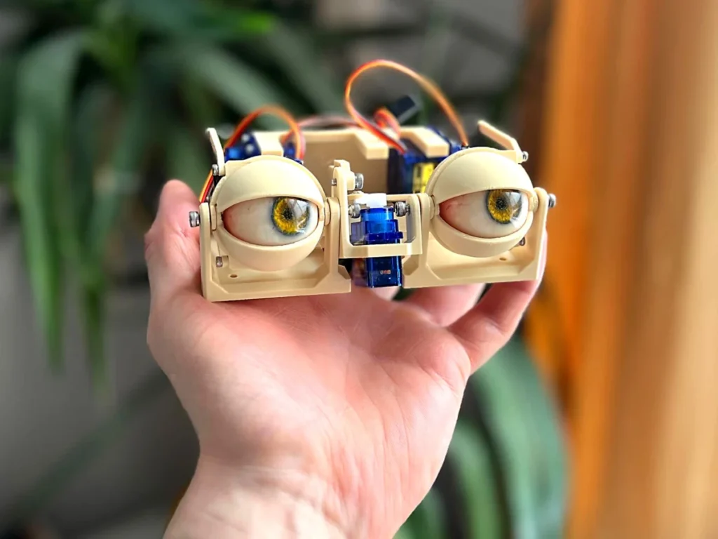
The intricate process of constructing sophisticated animatronic eyes, crucial for imparting lifelike expression to robotic figures and interactive displays, has been meticulously detailed in a recent guide, offering a profound insight into the mechanics and precision required for such endeavors. This comprehensive instructional breakdown, which leverages readily available components and accessible fabrication techniques, serves as a vital resource for hobbyists, educational institutions, and professional prop makers aiming to replicate the subtle nuances of ocular movement and eyelid articulation. The guide, exemplified by high-resolution photographic documentation, walks creators through the sequential assembly of various mechanical linkages and electronic actuators, culminating in a functional and expressive animatronic eye system.

The Architectural Foundation of Animatronic Vision
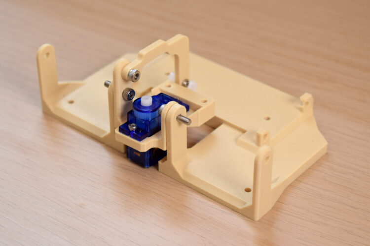
The genesis of any complex animatronic system lies in its foundational structure, which dictates the range and fidelity of its movements. For these animatronic eyes, the initial phase focuses on establishing the primary pivot points that enable multi-axis motion. The vertical, or y-axis, movement of the eye—encompassing both upward/downward gaze and the synchronized motion of the eyelids—is anchored by connecting two core bases. This pivotal connection is achieved using 10mm or 12mm M3 bolts, selected for their optimal length and robust threading, ensuring a stable yet fluid rotational axis. The choice of M3 bolts, a standard in precision engineering and robotics, underscores the necessity for secure fastening while allowing for smooth rotational dynamics critical for naturalistic motion. The specific lengths are vital to ensure adequate engagement with the components without protruding excessively or limiting movement.
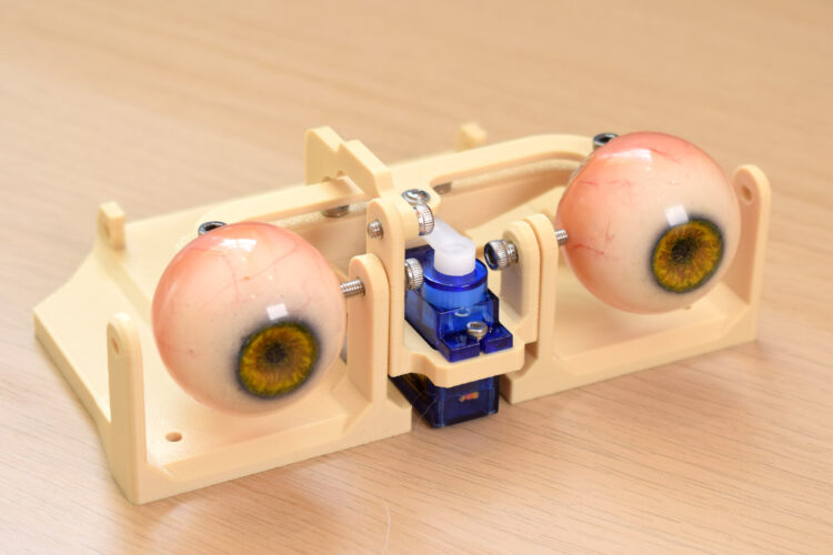
Following the establishment of the y-axis pivot, the horizontal, or x-axis, motion is integrated. This crucial movement, responsible for left-to-right eye tracking, is powered by a micro servo motor. The guide specifies placing the servo in a precise position and securing it with 4mm or 6mm M2 screws. Servo motors, particularly models like the TowerPro SG90 often utilized in such projects, are compact, cost-effective, and provide sufficient torque for light mechanical loads, making them ideal actuators for small-scale animatronics. The M2 screws, being smaller in diameter, are appropriate for securing these miniature servos without stripping their delicate mounting points, while the varying lengths (4mm or 6mm) allow for flexibility based on the thickness of the mounting material and the specific servo model’s flange design. This dual-axis approach mirrors the biological complexity of the human eye, which operates on a spherical joint allowing for a wide range of rotational movement, albeit simplified for mechanical replication.
Precision Linkages: Crafting Expressive Movement
The next series of steps delves into the intricate web of linkages that translate servo rotation into nuanced eye and eyelid movements. A key component, the y-axis arm, is meticulously attached to a sub-base using a 4mm, 5mm, or 6mm M3 screw. This component is pivotal as it transmits the vertical motion from its designated servo to the eye assembly. To this arm, a servo horn—a small lever that attaches to the servo’s output shaft—is secured on the third hole from its center, using a 4mm or 6mm M2 screw. The selection of the "third hole" is not arbitrary; it’s a critical design choice that determines the mechanical advantage and the range of motion. Positioning the servo horn further from the center increases the arc of movement, translating a smaller servo rotation into a larger physical displacement, which is often necessary for achieving the desired expressive range in animatronic eyelids or eye tilt. Creators are advised to meticulously check the orientation of all components at this stage, as misalignment can lead to binding, friction, or incorrect movement kinematics.
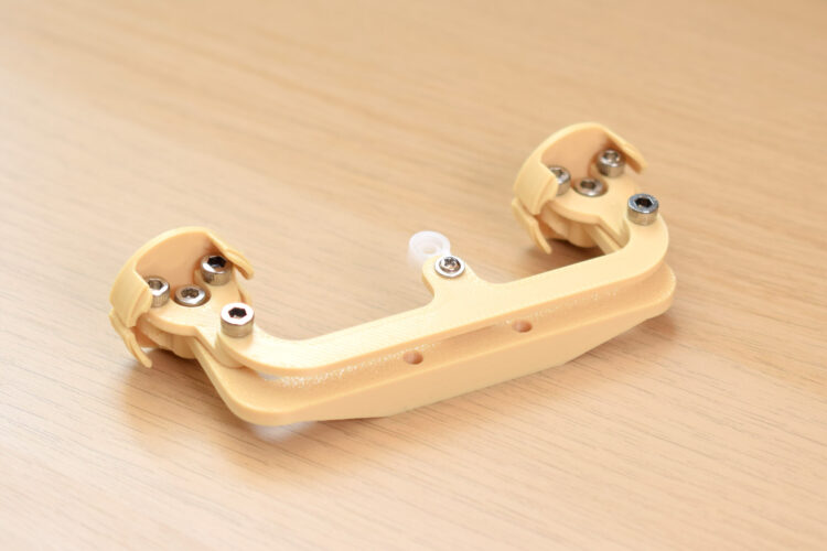
The construction of the x-axis assembly introduces another layer of mechanical complexity. This involves screwing "forks" into "eye-adaptors" using 4mm, 5mm, or 6mm M3 bolts. The design ingeniously accounts for manufacturing tolerances or specific material properties by specifying that the fork holes should be "oversized" so the screws can "bite into the adaptor." This technique, common in designs involving 3D-printed parts or softer plastics, creates a secure, self-tapping connection without requiring pre-threaded holes, simplifying assembly. The guide candidly notes that one bolt might need to be inserted at "a funny angle," highlighting the practical challenges and minor adjustments often encountered in hands-on fabrication projects. Such details are invaluable for makers, preparing them for potential minor hurdles and emphasizing the iterative nature of physical construction.
Integrating Vision and Articulation
With the primary axes and linkages established, the focus shifts to integrating the "vision" component—the animatronic eyes themselves—and refining their articulation. A "three-point connector" is attached to the top of the forks, with an M3 screw biting into an undersized hole, again leveraging the self-tapping principle for a secure fit. Crucially, a servo arm is attached to the final hole at the center of this three-point connector using a 5mm M3 bolt. This connection point is vital for transmitting the horizontal movement to the eyes. The guide notes a common modification: the servo arm hole may need to be drilled to 2.5mm–2.8mm to accommodate the screw. This highlights the reality of working with off-the-shelf components, where minor modifications are often necessary to achieve optimal fit and function, a testament to the problem-solving skills central to the maker ethos. Regular manipulation of the assembly during this stage is strongly recommended to identify and mitigate any friction, ensuring smooth and unhindered motion.
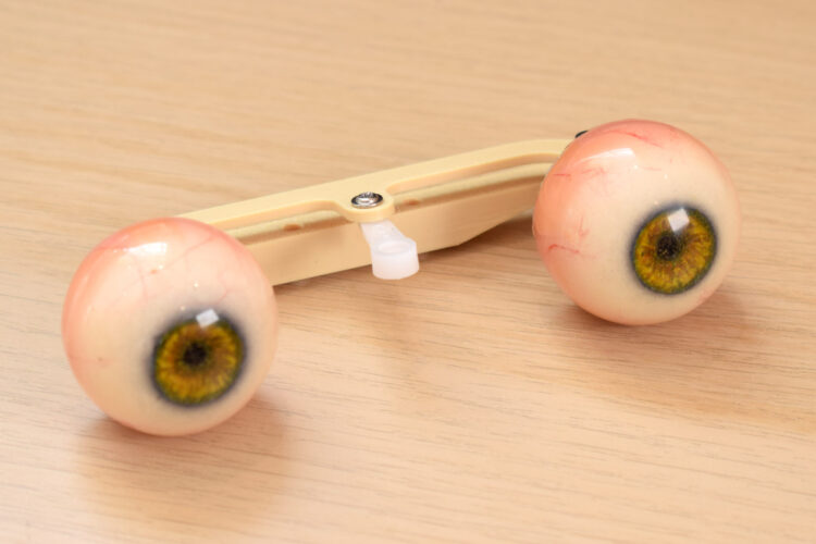
The "eye center-link," a component that bridges the movement to the individual eye units, is then attached to the eye adaptors with an 8mm M3 screw. Specific orientation is emphasized: the flat surface of the center-link must face upwards, and the sloping section downwards. This precise alignment is critical for correct mechanical leverage and to ensure that the eyes articulate within their intended range without obstruction. At this juncture, the actual animatronic eyes can be "plugged in," signifying the integration of the visual elements into the mechanical framework. This entire sub-assembly—the articulated eye mechanism—is then securely fastened to the center of the sub-base using two 12mm M3 bolts, creating a robust and unified core for the animatronic head.
The Nerve Center: Servo Block and Eyelid Control
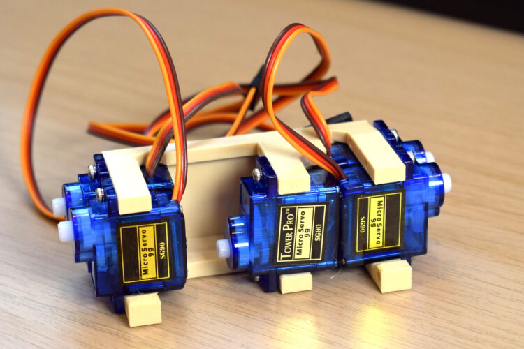
The sophistication of these animatronic eyes extends beyond mere gaze, incorporating lifelike eyelid movements for enhanced realism and expressiveness. This is achieved through a dedicated "servo block," which houses multiple micro servos—typically five TowerPro SG90 servos are specified—all meticulously oriented as shown in accompanying visual aids. This block, the "nerve center" for finer movements, is then attached to the main base using four M3x10mm bolts. The use of multiple servos dedicated to eyelids underscores the complexity involved in mimicking human facial expressions, where subtle changes in eyelid position can convey a vast array of emotions, from surprise to contemplation.
Identifying the correct eyelid components is paramount, often guided by photographic references. Once distinguished, the relevant connector for each eyelid is secured with a 4mm or 6mm M2 screw. A servo arm is subsequently attached to the other end of this connector, utilizing the last hole in the servo horn. Similar to previous steps, the guide anticipates the need for modification, suggesting that this particular servo horn hole might require drilling to 1.5mm–1.8mm. This finer drilling specification indicates the need for even greater precision in the eyelid mechanism, where smaller movements have a disproportionately large impact on the perceived realism of the animatronic character. Finally, the eyelids are attached to the base, completing the mechanical assembly, though the connection of the servo horns to their respective servos is deferred to a later, likely calibration, stage.
Broader Implications and the Rise of Accessible Animatronics
The detailed instruction set for these animatronic eyes, published by outlets such as Makezine, reflects a significant trend in the global maker movement: the democratization of advanced robotics and engineering. Historically, animatronics was the exclusive domain of large entertainment corporations like Disney, requiring vast resources and specialized expertise. However, the advent of affordable microcontrollers (like Arduino or Raspberry Pi), low-cost servo motors (such as the ubiquitous TowerPro SG90), and accessible digital fabrication techniques (primarily 3D printing) has dramatically lowered the barrier to entry. This shift has empowered individual creators, small studios, and educational institutions to develop sophisticated animated characters with unprecedented ease.
The educational implications are particularly profound. Projects like these serve as tangible, engaging platforms for teaching fundamental STEM concepts. Students and hobbyists gain hands-on experience in mechanical design, understanding principles of leverage, pivot points, and linkages. They delve into electronics by wiring servos and potentially integrating microcontrollers for programming movement sequences. The iterative nature of the build process, including troubleshooting minor misalignments or component modifications, fosters critical thinking and problem-solving skills that are invaluable in any engineering discipline. Experts in robotics education frequently emphasize the importance of project-based learning, noting that it not only imparts technical skills but also cultivates creativity and persistence.
Furthermore, the publication of such detailed guides supports a broader culture of open-source hardware and knowledge sharing. This collaborative environment accelerates innovation, allowing subsequent creators to build upon existing designs, refine techniques, and push the boundaries of what is achievable with accessible technology. The global market for hobbyist electronics and DIY robotics continues to expand, driven by this accessibility and the increasing sophistication of readily available components. This project, with its focus on realistic ocular and palpebral articulation, represents a significant step towards creating more expressive and emotionally resonant animatronic figures for a diverse range of applications, from educational tools and interactive art installations to independent film productions and intricate theatrical props. The commitment to providing precise measurements and photographic guidance ensures that aspiring animatronic engineers can confidently embark on this journey, transforming inert materials into captivating, lifelike creations.