The world of fractional-horsepower gearmotors is defined by a nuanced set of application requirements, often demanding highly specific performance characteristics from compact and efficient drive systems. Among these, the integration of worm gearing for its perceived "self-locking" attribute is a recurring design choice, particularly when engineers seek a mechanism to hold a load in position without continuous power input. However, this characteristic of worm gears, while undeniably valuable, is frequently misunderstood and, consequently, misapplied in critical motion control systems, leading to potential safety hazards and operational inefficiencies.
Understanding the Mechanics of Worm Gears and "Self-Locking"
At its core, a worm gear assembly consists of a worm (a screw-like shaft) that meshes with a worm wheel (a gear resembling a spur gear but with curved teeth designed to mate with the worm). This configuration typically provides a high reduction ratio in a compact, right-angle form factor. The "self-locking" phenomenon arises from the inherent friction and the geometry of the worm and wheel interface. When the worm drives the wheel, power is transmitted efficiently. However, under certain conditions, particularly when the lead angle of the worm is sufficiently small (typically less than 5 degrees) and the coefficient of friction between the meshing surfaces is high enough, the worm wheel cannot "backdrive" the worm. This means that a force applied to the output shaft (the worm wheel) will not cause the input shaft (the worm) to rotate.
This unidirectional power transmission is what engineers refer to as "self-locking." It offers an attractive solution for applications where a load must be held in position when the motor is de-energized, eliminating the need for a separate, continuously engaged holding brake. Manufacturers like Bodine Electric Co. produce DC gearmotors featuring worm gear assemblies, which are popular in various industrial and commercial products for their space-saving design and inherent static holding capability.

The Critical Misconception: Static Hold vs. Dynamic Braking
The prevalent misunderstanding stems from a critical distinction: the locking behavior of worm gears is primarily exhibited from a static (stopped) state. Many OEM design engineers mistakenly believe that if a self-locking gearbox is installed, cutting power to the motor will result in an immediate and controlled stop, with the axis subsequently holding its position securely. This assumption dangerously conflates "static self-locking" with "dynamic braking."
Dynamic braking, in the context of electromechanical design, refers to an active process by which a system decelerates and comes to a halt. This involves dissipating the kinetic energy of the moving mass. A self-locking worm gearmotor-driven axis, particularly one with significant inertia, will not instantaneously stop when power is removed. Instead, its existing kinetic energy will continue to drive the system, causing it to coast or freewheel until friction or another external force eventually brings it to a complete stop. Only once the system has reached a dead stop does the static self-locking characteristic of the worm gear engage, preventing backdriving.
This distinction is paramount for safety and operational integrity. In scenarios where immediate and controlled stopping is required, relying solely on the static self-locking property of a worm gear can lead to hazardous conditions, uncontrolled movement, and potential damage to equipment or injury to personnel. The inertia of the moving load, combined with the momentum, will overcome the initial resistance of the worm gear until the speed is low enough for the static friction to dominate.
The Indispensable Role of True Braking Systems

Given the limitations of self-locking gearmotors for dynamic stopping, true braking mechanisms become indispensable in a wide array of applications. Dynamic braking, as understood in this context, refers to the electromechanical design’s ability to actively slow or stop an axis, distinct from electrical braking methods that render an electric motor a generator for kinetic-energy dissipation via resistors or regenerative means.
Industrial brakes come in various forms, each suited for different applications:
- Electromagnetic Brakes: Often spring-applied and electromagnetically released, these brakes provide a fail-safe mechanism, engaging automatically when power is cut. They are commonly used for holding loads and emergency stopping.
- Hydraulic/Pneumatic Brakes: These systems use fluid pressure to actuate braking mechanisms, offering high stopping power and precise control, often found in heavy machinery.
- Friction Brakes (Disc, Drum): Similar to automotive brakes, these rely on friction materials to convert kinetic energy into heat, effectively slowing and stopping motion.
The integration of a dedicated brake ensures controlled deceleration, rapid stopping, and reliable holding. This combination addresses both dynamic stopping and static holding requirements, offering a comprehensive safety solution.
Case Studies: Where Self-Locking and Brakes Work in Tandem
Several real-world applications highlight the necessity of combining a self-locking gearbox with an actual brake to meet stringent safety and operational demands.

Stair Lifts and Mobility Applications:
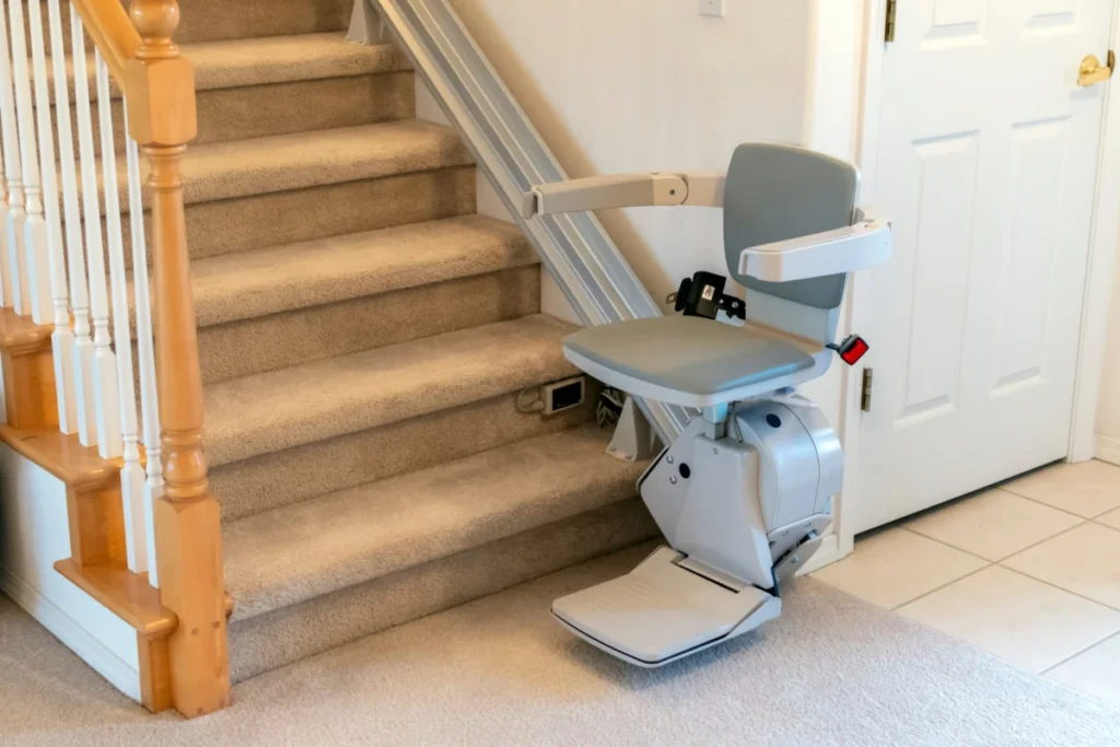
Stair lifts, designed to assist individuals with mobility challenges, represent a prime example. The safety of the user is paramount, necessitating precise control over movement, stopping, and holding. During normal operation, the gearmotor drives the chair up or down. If power is interrupted, or an emergency stop is initiated, the lift must decelerate quickly and come to a complete halt. A dedicated brake is crucial for this rapid and controlled stopping action, preventing any uncontrolled descent or ascent due to inertia. Once stopped, the self-locking worm gearbox can then reliably hold the chair in its exact position without continuous electrical input, ensuring stability and preventing creep, even under load. This dual mechanism ensures that the lift remains stationary and secure, protecting the user from falls or sudden movements. Regulatory bodies, such as those that enforce ASME A17.1/CSA B44 safety codes for elevators and escalators (which often inform stairlift standards), mandate robust braking systems and fail-safe designs for passenger safety.
Rotisserie Ovens:
Commercial rotisserie ovens, used for roasting poultry or other meats, also demonstrate this principle. When an operator opens the oven door, the turning of the meat spits must immediately pause to prevent burns and allow safe access. However, due to uneven weight distribution (e.g., two chickens on one side and none on the other), gravity could cause the spits to continue rotating even after the motor is de-energized. Here, a brake is essential to bring the rotisserie spits to a full, immediate stop. Subsequently, the self-locking gearbox holds them firmly in place, preventing any further rotation until the door is closed and the cooking cycle resumes. This ensures operator safety and proper product handling.
Other Industrial Applications:
Beyond these specific examples, numerous industrial designs benefit from this synergistic approach. Conveyor systems carrying heavy or delicate loads may require precise stopping at designated points, followed by a secure hold. Medical equipment, such as adjustable beds or imaging tables, demands both smooth, controlled movement and absolute stability when stationary. In these scenarios, the brake handles the dynamic stopping, and the self-locking gearmotor provides the static holding, often contributing to energy efficiency by allowing the motor to be de-energized while the load remains secured.
The Opposite Requirement: Backdrivability
While self-locking is a desired feature in many applications, other designs critically require the opposite: full backdrivability. This means that an external force applied to the output shaft can easily drive the input shaft. While engineers don’t typically ask for "backdrivable gearing" outright, the need for low resistance to backdriving is often articulated in terms of failsafe operation or manual override capabilities.

Railroad Crossing Gates:
Railroad crossing gates epitomize the need for backdrivability in a safety-critical context. These gates have extremely strict requirements for how easily gravity brings the arms down. In the event of a power failure, it is absolutely crucial that the gates automatically fall to block vehicle traffic, as no other signal will alert drivers of an oncoming train. This function relies on a gearbox that is so easily backdriven that the weight of the arm, combined with its counterbalances, can pull it down into its failsafe position. The design of these systems is complex, balancing the need for a relatively small, low-power motor to lift the arm against the imperative for gravity to lower it during an emergency. The gearbox must offer minimal resistance to backdriving to ensure this life-saving function.
Parking Barrier Gates:
Similarly, barrier-arm gates on parking garages often require backdrivability. If the gate’s electronics fail, or if an attendant needs to manually lift the gate (for instance, if a driver loses their ticket or there’s an emergency), the electromechanical assembly, including the motor’s gearbox, must be backdrivable. This allows for manual intervention, preventing vehicles from being trapped or ensuring smooth traffic flow during system malfunctions. Without backdrivability, manual operation would be impossible, requiring more complex and potentially costly override mechanisms or risking significant operational disruption.
Industry Perspectives and Best Practices
The confusion surrounding "self-locking" gearmotor behavior is a persistent challenge in the motion control industry. Recognizing this, many manufacturers, including Bodine Electric Co., actively work to educate their customers. Experts like Terry Auchstetter from Bodine Electric Co. emphasize the importance of direct consultation between application engineers and OEMs. These specialists guide designers through the nuances of gearmotor selection, ensuring that the chosen solution precisely matches the application’s requirements, especially regarding safety and operational dynamics.
To mitigate misapplication, some manufacturers have even begun to de-emphasize the term "self-locking" in their general product descriptions, instead focusing on the specific performance characteristics (e.g., static holding torque) and clearly delineating when a separate braking solution is necessary.

The trend in modern motion control design leans towards integrated solutions that combine motors, gearboxes, and brakes into a single, cohesive unit. This approach simplifies installation, ensures compatibility, and provides a more reliable and compact system that inherently addresses both dynamic stopping and static holding requirements. Furthermore, robust risk assessments and design reviews are critical steps in the development process for any motion control system, particularly those in safety-critical applications. These reviews ensure that all potential failure modes, including those related to braking and holding, are thoroughly evaluated and mitigated.
Broader Impact and Implications
The correct understanding and application of self-locking gearmotors versus dedicated brakes have far-reaching implications across several fronts:
- Safety: The most critical implication. Misunderstanding these concepts can lead to uncontrolled motion, equipment damage, and severe injury or even fatalities, especially in systems interacting with humans or handling heavy loads. Adherence to safety standards (e.g., ISO 13849 for machine safety, IEC 61508 for functional safety) is paramount.
- Design Efficiency and Cost: Proper selection prevents over-engineering (e.g., adding an unnecessary brake where static holding suffices) or, more dangerously, under-engineering (relying on self-locking for dynamic stops). This impacts bill of materials, system complexity, and overall cost.
- Reliability and Longevity: Using components for their intended purpose ensures optimal performance and extends their operational lifespan. Misapplying a self-locking gearmotor for dynamic braking can lead to premature wear and failure of the gearbox components due to excessive stress.
- Regulatory Compliance: Many industries are governed by strict safety regulations and standards. Designs that fail to incorporate appropriate braking mechanisms when required can lead to non-compliance, legal liabilities, and market exclusion.
In conclusion, while the self-locking characteristic of worm gearmotors offers genuine benefits for static load holding, it is fundamentally distinct from dynamic braking. OEM design engineers must rigorously evaluate their application’s specific requirements for both controlled deceleration and static position holding. Engaging with experienced application engineers and understanding the fundamental physics of motion control systems are essential steps to ensure that designs are not only efficient and cost-effective but, most importantly, safe and compliant. The distinction between a static hold and an active stop is not merely semantic; it is a critical engineering principle that underpins the integrity and safety of countless electromechanical systems worldwide.