In the intricate world of industrial automation and mechanical design, fractional-horsepower gearmotors serve as the workhorses behind countless applications, from medical equipment to consumer goods and specialized machinery. These compact yet powerful units are meticulously engineered to meet unique operational demands, often requiring precise control over motion, speed, and position. Among the various types, gearmotors incorporating worm gearing are frequently specified by OEM design engineers due to an inherent characteristic often referred to as "self-locking." However, this locking behavior, while beneficial in specific contexts, is one of the most widely misunderstood and consequently misapplied features in motion control, leading to potential safety hazards and operational inefficiencies.
Understanding Fractional-Horsepower Gearmotors and Worm Gearing
Fractional-horsepower gearmotors, typically defined as those producing less than one horsepower, are ubiquitous in scenarios demanding controlled, lower-power motion. They integrate an electric motor with a gearbox, providing a compact solution for torque multiplication and speed reduction. Their applications span a vast spectrum, including conveyor systems, medical beds, laboratory stirrers, automatic door openers, and even complex robotic joints. The choice of gearbox type – be it spur, helical, planetary, or worm – depends critically on the specific performance requirements of the application, such as efficiency, noise, backlash, and the desired reduction ratio.
Worm gearing, a subset of right-angle gearing alongside hypoid assemblies, consists of a "worm" (a screw-like input gear) meshing with a "worm wheel" (a spur-like output gear). This configuration offers several distinct advantages: high reduction ratios in a single stage, compact size, quiet operation, and a significant change in the axis of rotation (typically 90 degrees). However, the most compelling, and often misinterpreted, characteristic of worm gears is their potential for "self-locking." This phenomenon arises from the geometry of the worm and wheel, specifically the helix angle of the worm and the friction coefficient between the mating surfaces. When the helix angle is sufficiently small and the friction high, the worm wheel cannot rotate the worm, effectively preventing backdriving from the output side.
The Critical Misconception: Static Self-Locking vs. Dynamic Braking

The core of the misunderstanding lies in conflating static self-locking with dynamic braking. A common misconception among some engineers is the belief that "if I get a self-locking gearbox, when I cut power, the axis will come to a quick stop and will hold its position." This premise, while intuitively appealing for simplifying designs, overlooks a fundamental principle of physics: inertia.
-
Static Self-Locking: This characteristic describes a worm gear’s ability to resist motion from the output side when the system is already at a dead stop. It means that an external load applied to the output shaft will not cause the input worm to rotate, provided the load does not exceed the static friction and the "lock" condition is met by the gear’s design parameters (e.g., helix angle and material friction). The system effectively holds its position without continuous power input to the motor. This holding capability is a passive function, reliant on the gear geometry and material properties to prevent back-drive. It is most effective when the system is stationary or moving at very low speeds where inertial forces are negligible.
-
Dynamic Braking: In contrast, dynamic braking refers to the active process of slowing down and stopping a moving load. This involves dissipating the kinetic energy of the moving system. Dedicated braking mechanisms, such as electromagnetic brakes, eddy current brakes, or friction brakes, are designed specifically for this purpose. When electrical input to a motor is removed, or an emergency stop is initiated, a dynamic brake applies a controlled resistive force to rapidly bring the system to a halt. The energy dissipated is typically converted into heat.
The critical distinction is that a worm gearmotor-driven axis possesses inertia. Even if the gear assembly is designed to be self-locking in a static state, this inertia will keep the axis turning for a period after electrical input is removed. The "self-locking" characteristic only becomes effective once the system has already decelerated to a stop. It does not actively dissipate kinetic energy to cause the stop. The deceleration time and distance will depend solely on the system’s inertia and any inherent friction losses in the system, not on the worm gear’s self-locking property. Therefore, relying on a self-locking worm gear for dynamic braking is akin to expecting a parking brake to stop a moving car – it’s designed for holding, not for active deceleration.
The Dangers of Misapplication: Safety and Operational Risks
The misapplication of self-locking gearmotors as dynamic brakes carries significant risks, potentially leading to critical safety failures, equipment damage, and regulatory non-compliance.

-
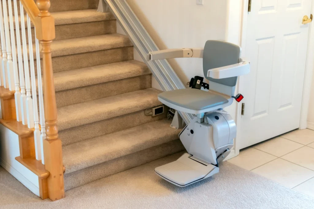
Safety Hazards: In applications where sudden and controlled stopping is paramount for human safety, such as lifts, conveyors, or medical devices, relying solely on a self-locking gearbox is extremely dangerous. An uncontrolled rundown of a system due to inertia can cause severe injuries to operators or users. For instance, a stairlift intended to stop instantly upon a safety sensor trigger might continue to move for several inches or feet if only a self-locking gear is present, posing a grave risk to the passenger.
-
Equipment Damage: Components not designed for dynamic braking stresses can suffer premature wear or catastrophic failure. If a system is repeatedly subjected to uncontrolled rundown and then abruptly "catches" when the worm gear eventually locks, it can induce shock loads throughout the mechanical train, leading to fatigue, breakage, or misalignment of gears, bearings, and shafts. This translates to increased maintenance costs, downtime, and a shortened lifespan for the machinery.
-
Loss of Control and Performance Degradation: Systems requiring precise positioning or rapid stopping for process control will exhibit poor performance if a self-locking gearbox is expected to perform braking duties. The inability to stop accurately or quickly can lead to production errors, reduced throughput, and quality control issues in manufacturing environments.
-
Regulatory Non-Compliance: Many industrial and consumer products are subject to stringent safety standards (e.g., ISO, OSHA, ANSI, European Machinery Directive). These standards often mandate specific braking performance, emergency stop capabilities, and redundant safety features. Designs that fail to incorporate dedicated braking mechanisms where required, relying instead on the misunderstood self-locking characteristic, will likely fail compliance audits, resulting in costly redesigns, product recalls, or legal liabilities.
When to Use Self-Locking Gearboxes (and How): Complementary Safety Systems
Despite the caveats, self-locking worm gears offer genuine benefits when correctly integrated into a broader motion control system. Their true value lies in their ability to hold a static position reliably, often without continuous power, which can be a critical advantage in power-off conditions or when maintaining a precise stance against external forces. This makes them excellent companions to actual braking systems, providing a layered approach to safety and functionality.

Case Study 1: Stairlifts and Mobility Applications
Consider certain stairlifts, as highlighted by industry leaders like Bodine Electric Co. These systems prioritize both efficiency and robust safety. When a stairlift needs to stop, perhaps due to a user input, a safety sensor activation, or a power interruption, it must do so quickly and smoothly. This dynamic deceleration is the role of an actual brake—often an electromagnetic brake that engages rapidly when power is cut. Once the stairlift has come to a complete stop, the self-locking worm gearbox takes over. It ensures that the carriage remains securely in place, even if power is completely lost, preventing any creep or rollback due to gravity or an occupant’s weight. This combination provides a critical layer of redundancy: the brake handles the dynamic stopping, and the self-locking gear provides static holding, ensuring the safety of the user. Such designs often adhere to stringent standards like ISO 9999 for assistive products.
Case Study 2: Rotisserie Ovens
Another compelling example is a rotisserie oven used for roasting meats. For safety, the turning of the meat spits must pause immediately when the oven door is opened, preventing burns from rotating hot items. Furthermore, if the load of chickens or other items is imbalanced, gravity could cause the spits to continue turning slowly even when the motor is de-energized. Here, a dedicated brake is essential to bring the rotisserie spits to a rapid, full stop as soon as the door opens or power is cut. Once stopped, the self-locking gearbox then reliably holds the spits in that precise position, overcoming any gravitational torque from an uneven load. This prevents accidental rotation, allowing for safe loading, unloading, and inspection of the food.
These examples underscore that the self-locking feature is not a substitute for dynamic braking but rather a valuable complement, enhancing safety and stability once a dynamic stop has been achieved. A holistic design approach integrates both components, leveraging their respective strengths.
The Opposite Requirement: Backdrivability and Failsafe Designs
Interestingly, some critical applications require the exact opposite of self-locking: full backdrivability. This means that an external force applied to the output shaft should be able to drive the input shaft and, consequently, the motor. While engineers don’t typically ask for "backdrivable gearing" outright, the need for low resistance to backdriving is often articulated through other requirements, particularly in failsafe mechanisms.
Case Study 1: Railroad Crossing Gates
Railroad crossing gates are a prime example of systems where backdrivability is paramount for safety. These gates have very strict requirements for how easily gravity brings the arms down. In the event of a power failure, it is absolutely critical that the gates descend rapidly and block vehicle traffic. This is because a power failure also means that no other signal system (like flashing lights or audible alarms) might be operational to alert drivers of an oncoming train. This essential failsafe function relies on a gearbox that is easily backdrivable. The design of these systems often includes counterbalances on the arms to minimize the motor’s power requirement for lifting, but the fundamental need for gravity to pull the arm down in an emergency necessitates a gearbox that offers minimal resistance to reverse motion. Regulatory bodies like the Federal Railroad Administration (FRA) mandate strict performance and safety standards for these critical infrastructure components.

Case Study 2: Parking Barrier Arms
Similarly, barrier-arm gates at parking garages often require backdrivability. In scenarios of power failure, system malfunction, or if a user loses their ticket, there must be a way to manually lift the gate. This can be achieved through electronics with override functions, but a mechanically backdrivable electromechanical assembly, including the motor’s gearbox, offers a robust failsafe. This allows an attendant to manually lift the gate, ensuring uninterrupted access or egress without requiring complex tools or system restarts. It balances security needs with practical operational demands and user convenience.
Engineering Best Practices and Design Considerations
Given the potential for confusion and the critical implications for safety and performance, engineering best practices dictate a rigorous approach to gearmotor selection and system design:
-
Holistic System Design: Motion control should always be viewed as a complete system, not a collection of isolated components. The interaction between the motor, gearbox, braking mechanism, control electronics, and the driven load must be thoroughly analyzed. Each component plays a specific role, and relying on one to perform the function of another can compromise the entire system.
-
Comprehensive Risk Assessment: Engineers must conduct thorough Failure Mode and Effects Analyses (FMEAs) and other risk assessments. This involves identifying potential failure modes (e.g., power loss, mechanical failure, control system error), analyzing their effects, and implementing mitigation strategies. For applications requiring a controlled stop, the absence of a dedicated brake, or the misapplication of a self-locking gear, should be flagged as a high-risk failure mode.
-
Dedicated Braking Mechanisms: When dynamic stopping is required, a dedicated brake is indispensable. Engineers must select the appropriate type of brake (e.g., electromagnetic, spring-applied, hydraulic) based on criteria such as required braking torque, response time, duty cycle, environmental conditions, and lifespan. Integrating the brake into the system’s control logic ensures coordinated and safe operation.

-
Redundancy for Critical Applications: In safety-critical applications, redundant systems are often mandated or highly recommended. This might involve multiple brakes, or a combination of an active brake and a passive self-locking gearbox, as seen in stairlifts, to ensure that a single point of failure does not lead to a catastrophic event.
-
Consultation with Manufacturers: Manufacturers like Bodine Electric Co. possess deep expertise in gearmotor design and application. Engaging with their application engineers early in the design process can provide invaluable insights, preventing costly mistakes and ensuring optimal component selection. They can guide OEMs on the proper use of self-locking characteristics and the integration of complementary braking solutions.
-
Adherence to Industry Standards: Staying abreast of and strictly adhering to relevant international, national, and industry-specific safety standards (e.g., IEC, UL, CE) is non-negotiable. These standards provide frameworks for safe design, testing, and operation of machinery.
The Evolving Landscape of Motion Control
The field of motion control is continually evolving with advancements in motor technology, power electronics, and intelligent control systems. Smart braking systems, regenerative braking, and sophisticated algorithms for predictive maintenance are enhancing both performance and safety. However, these technological leaps do not diminish the importance of understanding fundamental mechanical principles. The behavior of gears, the physics of inertia, and the distinction between static and dynamic forces remain cornerstones of reliable and safe engineering design.
Conclusion

The "self-locking" characteristic of worm gearmotors is a powerful and beneficial attribute when properly understood and applied. It excels at maintaining a static position, offering a reliable hold without continuous power input, making it an excellent component for securing loads once they are stopped. However, it is fundamentally distinct from dynamic braking, which is the active process of dissipating kinetic energy to bring a moving system to a halt. The persistent misconception that a self-locking gearbox can serve as a dynamic brake is a critical oversight with severe implications for safety, operational integrity, and regulatory compliance.
For engineers designing motion control systems, particularly those involving fractional-horsepower gearmotors, the message is clear: prioritize comprehensive system design. Where dynamic stopping is required, a dedicated braking mechanism is essential. The self-locking feature of worm gears should be considered a complementary safety measure for static holding, not a substitute for active deceleration. By embracing a nuanced understanding of these mechanical principles and collaborating with experienced manufacturers, engineers can ensure their designs are not only efficient and effective but, most importantly, safe and reliable. The insights shared by industry experts, such as Terry Auchstetter of Bodine Electric Co., are invaluable in guiding OEMs toward the proper and safe application of these critical components.