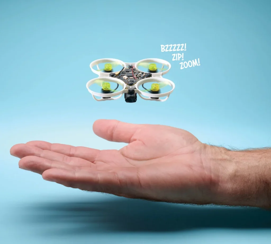
The landscape of First Person View (FPV) aviation has undergone a radical transformation over the last decade, transitioning from large, cumbersome outdoor platforms to miniaturized, high-performance "micro-drones" capable of navigating complex indoor environments. Central to this evolution is the "Tiny Whoop" class of aircraft—a category of sub-micro quadcopters characterized by ducted propellers and ultra-lightweight frames. The pursuit of peak performance in this category is a game of milligrams, where the removal of a single plastic connector can yield measurable improvements in agility and flight duration. This technical report details the assembly of a 13.5-gram ultralight FPV drone, examining the engineering choices and precision soldering techniques required to push the boundaries of micro-aviation.
The Physics of Micro-Aviation: Why Weight Matters
In the realm of FPV racing, the thrust-to-weight ratio is the primary metric of performance. For a drone powered by a single-cell (1S) lithium polymer battery, every gram of mass requires a corresponding increase in motor RPM to maintain a hover, which in turn depletes the battery faster and reduces the "punch" available for aggressive maneuvers. A standard micro-drone may weigh between 20 and 30 grams; however, by utilizing advanced "Maker" techniques, enthusiasts can reduce this weight by nearly 50%. The resulting 13.5-gram aircraft exhibits a level of responsiveness that mimics larger 5-inch racing drones, allowing for high-speed indoor racing and precision acrobatics.
Phase I: Flight Controller Modification and Weight Reduction
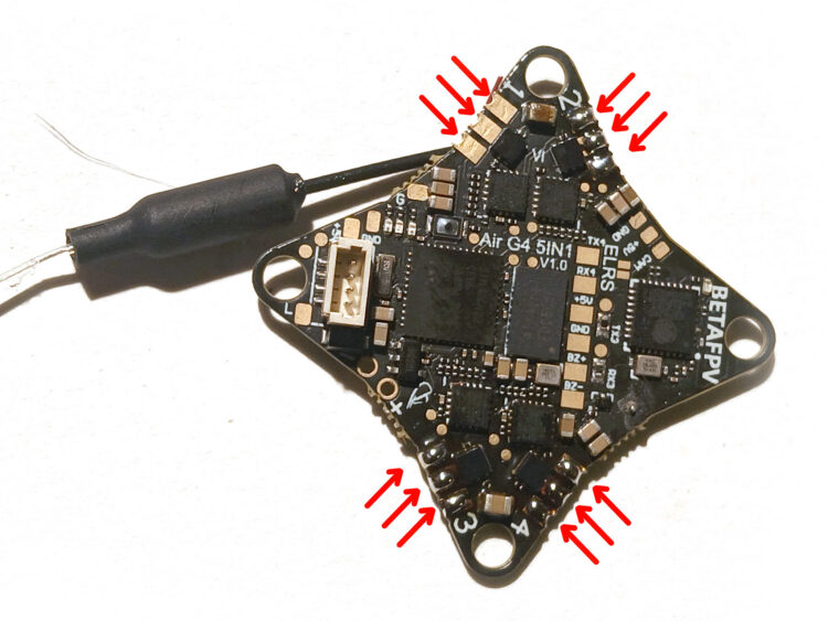
The assembly process begins with the "Matrix" flight controller, a sophisticated Printed Circuit Board (PCB) that integrates the flight processor, Electronic Speed Controllers (ESCs), and a radio receiver. To achieve an ultralight build, the builder must first engage in "de-pinning"—the removal of non-essential plastic components.
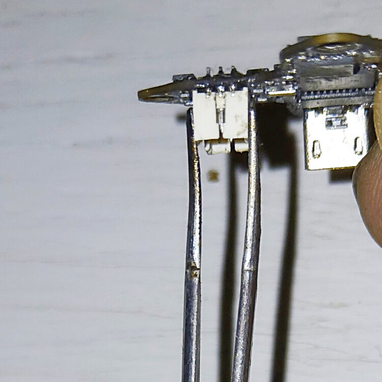
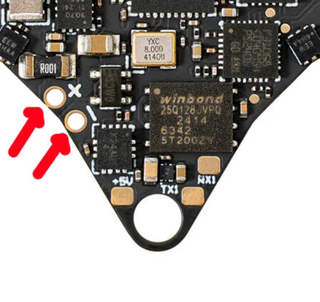
Technicians recommend securing the flight controller in a hobby vise or using "helping hands" to ensure stability. The primary targets for weight reduction are the motor connectors. While these plugs offer convenience for swapping motors, they add unnecessary mass and introduce electrical resistance. By removing these connectors and soldering the motor wires directly to the board, the builder ensures a more robust electrical connection and a lighter profile.
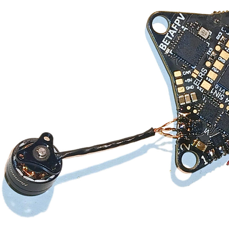
The removal process involves applying flux to the solder points and using clamping tweezers to apply downward tension on the connector. When the soldering iron heats the joints, the weight of the tweezers allows the connector to drop away cleanly. Residual solder is then removed using a copper wick, leaving clean pads for direct wire attachment.
Phase II: Precision Soldering and Propulsion Integration
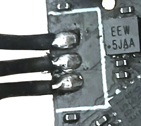
Once the board is prepped, the four motors must be integrated. This requires "tinning" the pads—applying a thin layer of fresh solder to the PCB to facilitate a quick, strong bond. Maintenance of the soldering iron tip is critical here; a clean tip ensures optimal heat transfer and prevents the accidental bridging of the tiny Surface Mount Device (SMD) components that populate the board.

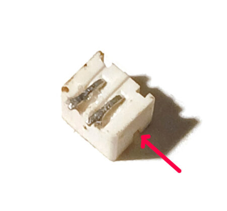
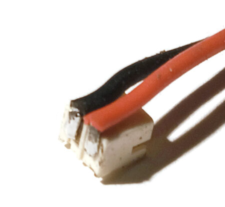
The motors are soldered to the underside of the flight controller. This orientation is strategic, keeping the center of mass low and protected within the frame’s nacelles. Following the motor installation, the focus shifts to the power lead. The industry-standard PH 2.0 battery connector is modified by bending the leads flat and soldering 1.6-inch high-strand-count silicone wires. Verification with a multimeter is essential at this stage to ensure correct polarity, as a reversed connection would instantaneously destroy the flight controller’s sensitive logic gates.

Phase III: Vision Systems and Voltage Regulation
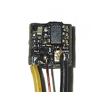
The First Person View experience is provided by an ultra-tiny CMOS camera and Video Transmitter (VTX) combo. Standard wiring provided with these cameras is often too thick and rigid for ultralight builds. Builders replace these with 1.3-inch silicone wires for ground and signal, and fine enameled "magnet wire" for power.
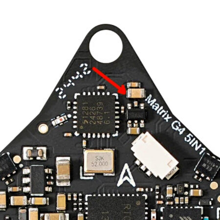
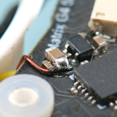
A significant technical hurdle in this build is voltage compatibility. While the flight controller is designed for 5V cameras, many ultra-lightweight FPV cameras require a 3.3V power source. To resolve this, the builder must tap into the board’s onboard 3.3V regulator, which is typically not broken out to a standard pad. This involves a high-precision solder joint on the left side of a specific SMD capacitor.
Furthermore, soldering the ground wire to the camera’s timing crystal requires extreme speed. Excessive heat can cause the crystal to desolder and slide off its pads, rendered the camera useless. This phase of the build highlights the intersection of hobbyist craft and professional electronic assembly.
Phase IV: Structural Assembly and Aerodynamic Tuning
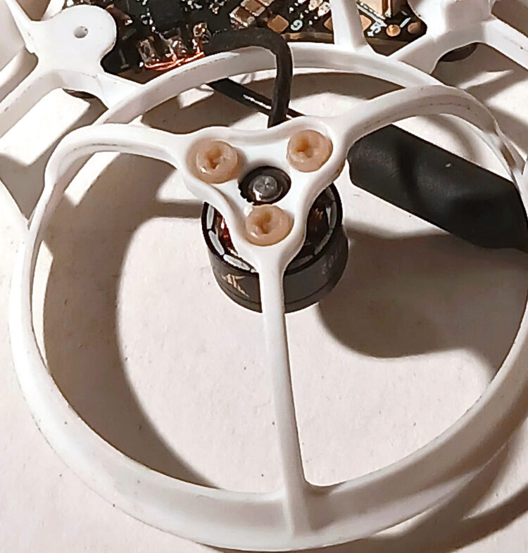
The frame of a Tiny Whoop serves as both the chassis and the protective ducting for the propellers. The flight controller is mounted using rubber grommets to provide vibration isolation, which is vital for the onboard gyroscopes to function accurately. The motors are secured into their nacelles using PEEK (Polyether ether ketone) plastic screws. PEEK is chosen for its high strength-to-weight ratio and its ability to withstand the heat generated by the motors, though builders are cautioned against over-tightening, as the heads can snap under excessive torque.
The camera is mounted to the front of the frame using E6000, a high-strength industrial adhesive that remains flexible when cured. This flexibility acts as a shock absorber during the inevitable crashes associated with FPV racing.
Antenna Theory and Custom Fabrication
The drone’s video range is determined by its antenna. While pre-made antennas like the "Hummingbird" are available, custom-length "linear whip" antennas are often preferred for weight savings. Based on the physics of radio propagation, a 1/4 wave antenna for the 5.8GHz frequency band must be precisely 12.92mm long. Builders use digital calipers to trim the active element of the coaxial cable to this exact specification, ensuring maximum signal resonance and minimal video interference.
Propeller Modification: The Two-Blade Advantage
Standard micro-drones often utilize three- or four-blade propellers for lift. However, in an ultralight build, a two-blade configuration is often superior. By using fingernail clippers to remove two opposing blades from a four-blade prop, the builder reduces the rotational mass (moment of inertia). This allows the motors to change RPM more rapidly, resulting in sharper handling and reduced "prop wash" (the turbulence a drone encounters when descending through its own air).

Chronology of a High-Performance Build
- Component Selection: Sourcing a high-spec 1S flight controller, 0802 or similar brushless motors, and a sub-2g camera.
- PCB De-pinning: Removing heavy plastic headers and connectors.
- Direct Soldering: Attaching motors and the power pigtail directly to the board.
- Voltage Tapping: Identifying and soldering to the 3.3V rail for camera power.
- Structural Mounting: Installing the FC with grommets and motors with PEEK screws.
- Adhesive Bonding: Mounting the camera with E6000 and allowing a 24-hour cure time.
- RF Tuning: Measuring and trimming the 5.8GHz whip antenna to 12.92mm.
- Software Configuration: Connecting to Betaflight to configure motor direction (Props-Out) and PID tuning.
Broader Impact and Industry Implications
The DIY drone movement, exemplified by projects like the 13.5-gram Whoop, has significant implications beyond the hobbyist community. The techniques developed here—specifically in the realms of miniaturization and weight optimization—are increasingly relevant to industrial inspection and search-and-rescue operations. Small, ducted drones are uniquely capable of navigating collapsed buildings or internal piping where larger GPS-dependent drones cannot fly.

Furthermore, the "Maker" culture surrounding FPV racing serves as a critical entry point for STEM education. Builders must master soldering, basic circuit theory, radio frequency (RF) physics, and PID (Proportional-Integral-Derivative) control loops. As the Federal Aviation Administration (FAA) continues to refine regulations, such as Remote ID requirements, the sub-250-gram category remains a vital "safe harbor" for innovation and recreational flight, as these micro-drones are generally exempt from many of the more onerous registration requirements.

Conclusion: The Future of the 1S Platform
The successful assembly of a 13.5-gram racing drone represents the current pinnacle of 1S (single-cell) engineering. By meticulously removing excess weight and optimizing every electrical connection, the builder creates an aircraft that defies the limitations of its size. As battery chemistry continues to improve and silicon integration becomes even denser, we can expect the benchmark for "ultralight" to drop even further, potentially bringing us into the era of sub-10-gram high-performance FPV aircraft. For now, the 13.5-gram Whoop stands as a testament to the power of precision making and the relentless pursuit of flight efficiency.