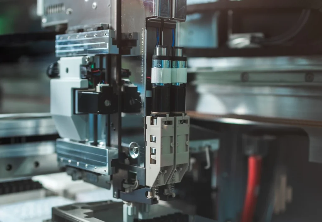
Automated motion systems, the intricate orchestrators behind everything from sophisticated industrial robots to precise medical devices, represent a fundamental pillar of modern technological advancement. These systems, whether performing repetitive tasks in a manufacturing plant or executing delicate movements in a laboratory, are fundamentally electric-motor-driven designs built upon a combination of mechanical and electronic components. Understanding their core principles is essential for engineers and technologists navigating the rapidly evolving landscape of automation.
Defining the Landscape: Power Transmission vs. Motion Systems
The industry distinguishes between two primary categories of automated designs: power-transmission systems and motion systems. While both are integral to automated operations, their emphasis and component priorities differ significantly.
Power-transmission designs are characterized by a focus on raw torque, force, and speed. In these systems, mechanical components often dominate the build, engineered to efficiently transfer power from a motor to a load with minimal loss. Examples include conveyor belts moving heavy goods, large pumps circulating fluids, or simple gear trains designed for mechanical advantage. The primary goal is robust and efficient power delivery, often with less emphasis on intricate positional control.
In contrast, motion systems prioritize precise positioning and controlled motion profiles. These systems are defined by their ability to execute specific speeds, accelerations, jerk rates, and complex speed-torque profiles, alongside routines like homing. The control electronics and feedback mechanisms play a critical role, ensuring that movements are not just powerful, but also accurate, repeatable, and synchronized. This category encompasses applications like robotic arms performing intricate assembly, CNC machines cutting with micron-level precision, and automated guided vehicles (AGVs) navigating complex warehouse layouts. The distinction highlights a broader trend in automation towards greater intelligence and precision, moving beyond brute force to finely tuned control.
These sophisticated design types are pervasive, forming the operational backbone of countless consumer products, advanced office automation equipment, critical medical devices, and high-throughput laboratory automation equipment. In the industrial sector, they are the bedrock of discrete factory automation.
Discrete vs. Process Automation: Tailoring Motion to Application
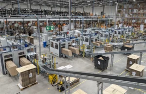
Further differentiation arises when considering the type of factory automation. Discrete factory automation involves the working, machining, assembling, testing, capping, wrapping, packaging, labeling, counting, scanning, and transporting of individual, separate workpieces or products. Each item undergoes a sequence of distinct operations before completion. Industries like automotive manufacturing, electronics production, automated warehousing, and consumer goods packaging are prime examples. Here, motion systems are indispensable, ensuring the precise handling, placement, and manipulation of individual components or finished goods throughout the production line. For instance, in automotive assembly, robotic arms employ motion systems to weld car frames with extreme accuracy, while in electronics, pick-and-place machines use vision-guided motion systems to position tiny components on circuit boards.

Conversely, process automation deals with continuous systems involving fluids, gases, powders, or batches subject to ongoing chemical reactions, temperature controls, metering, and flow operations. These systems are generally difficult to stop and start without significant disruption. Industries such as mining, energy (including coal and nuclear power generation), oil and gas, large-scale food processing, pharmaceutical and chemical manufacturing, glass and ceramic production, plastics, textiles, and wood and paper processing are heavily reliant on process automation. While motion components exist within these environments (e.g., valve actuators, conveyor drives), the overarching control philosophy differs from the precise, start-stop, positional control inherent in discrete motion systems. Motion system designs are, therefore, primarily associated with discrete automation, delivering the precise placement and transport critical for individual product manufacturing and handling.
The Design Imperative: Precision and Performance
The successful design of an automated motion system commences with a meticulous quantification of the physical parameters governing the desired movement. This initial phase, often iterative, lays the groundwork for component selection and system optimization.
Quantifying Loads and Inertia: Engineers must first thoroughly document the loads to be moved, including their mass, dimensions, and any external forces acting upon them. Crucially, the inertia involved must be calculated. Inertia, an object’s inherent resistance to changes in its state of motion (acceleration or deceleration), is a critical factor. The total inertia encompasses both the workpiece load and the moving parts of the axis itself. This can vary dramatically. For example, a direct-drive torque motor or a linear motor, which has no intermediate mechanical components, might exhibit very low reflected inertia. However, systems incorporating gearsets for speed reduction or for inertia matching (a servotuning technique) will have higher reflected inertia.
Mechanical power transmission elements further complicate inertia calculations. Tangential forms of power transmission – such as synchronous belt-and-pulley systems, rack-and-pinion sets, and chain-and-sprocket drives – each contribute unique inertial values. Similarly, linear actuators employing leadscrews, ballscrews, or roller screws also have distinct inertial characteristics. Engineers must sum all axis components’ inertias and reflect them back to the motor’s output shaft, as this is the critical location where the motor must generate sufficient torque to overcome this resistance. A particularly challenging scenario involves changing inertia, common in applications like robotic dispensing or machining tasks where the mass of the end-effector changes as material is added or removed. Such systems often require advanced servotuning algorithms to dynamically compensate for these varying dynamics, ensuring stable and accurate performance.
Defining Motor Output Force and Torque: Following inertia quantification, the next crucial step is to define the required motor output force (for linear motors) or, more commonly, torque (for rotary motors). This allows for the proper sizing of the electric motor on each axis. The motor must generate sufficient acceleration torque to overcome inertia and friction to reach the desired speed quickly. Furthermore, it must deliver adequate constant torque during the run phases to maintain speed against resistive forces and provide sufficient deceleration torque for controlled stopping. These torque requirements are analyzed over the entire motion profile, including any dwell times, to ensure the motor can perform its duty cycle without overheating or failing to meet performance specifications.
The Intelligence Behind Motion: Controls and Drives
The commands that govern motor actions are executed by system motor controls or motion controls. Over the past two decades, these two technologies have seen significant convergence, often integrating into unified platforms. Both accept low-power signals and transform them into actuation-level electrical outputs to drive the motors.

Metaphorically, if an automated motion system were an organism, the motion controller would serve as its brain. It monitors sensor feedback, commands precise movements, and integrates various system components. Its core functions include:
- Trajectory generation: Creating the ideal path and speed profile for movement.
- Axis synchronization: Coordinating multiple axes to work in unison for complex movements.
- Error correction: Continuously adjusting motor output based on feedback to minimize deviations from the commanded path.
- Sequence management: Executing pre-programmed routines and responding to real-time inputs.
- System diagnostics: Monitoring operational parameters for fault detection and predictive maintenance.
Control Architectures: Centralized vs. Distributed: Motion controllers can be arranged in various architectures, mirroring the nervous systems of animals.
- Centralized controls house the main controller, motor drives, and other complementary electronics together in a single control cabinet. This traditional approach often offers cost efficiencies for compact machine installations and simplifies initial programming due to a unified processing unit. However, for systems with many axes spread over a large area, it can lead to extensive and costly wiring, as well as larger control cabinets.
- Distributed drive-based controls decentralize the intelligence and power, often integrating drives directly onto or near the motors. This architecture can significantly trim wiring issues and costs, reduce cabinet size, and improve system modularity. It is particularly beneficial for machines with numerous axes, complex geometries, or those requiring high-speed, localized control. The choice between centralized and distributed controls is a critical decision made during the iterative design process, balancing factors like footprint, wiring complexity, real-time performance, and maintenance considerations.
Regardless of the chosen architecture, each motor’s drive (whether a dedicated motor control or amplifier) must possess the capability to provide both acceleration current and continuous current sufficient to satisfy the motion design’s duty-cycle requirements. This includes not only the power to move the load but also the capacity to dissipate heat generated during operation, especially when slowing the load. Drive sizing rigorously accounts for RMS (root mean square) current and peak acceleration current, while also considering any increase in the motor’s winding resistance due to thermal effects, which can degrade performance and efficiency.
The Special Case of Servosystems: Unlocking Dynamic Precision
Motion system designs configured as closed-loop systems, commonly known as servosystems, represent the pinnacle of dynamic, precise control. These machines excel in applications demanding quick accelerations and decelerations, as well as operation in all four design quadrants. The "four quadrants" concept is an industry standard indicating a design’s ability to precisely control an axis across all combinations of positive and negative torques and speeds (e.g., forward acceleration, forward deceleration, reverse acceleration, reverse deceleration). This comprehensive control ensures smooth, stable, and highly responsive movement throughout the entire operational envelope.
Sizing such servosystems necessitates a holistic systems approach that concurrently evaluates mechanical, electrical, and software parameters. The mechanical system dictates the loads and inertias; the electrical system (motor and drive) must be capable of delivering all necessary continuous (RMS) and acceleration (peak) currents to meet those demands; and the software (motion controller and algorithms) orchestrates the precise execution of movements. Any imbalance in these three pillars can compromise system performance, leading to instability, reduced accuracy, or premature component wear.
Environmental Resilience and Component Selection
The operational environment profoundly impacts the longevity and reliability of a motion system. Where a design is destined for hot, dusty, washdown, vacuum, explosive, or other challenging industrial environments, the selection of power-transmission, electromechanical, and electronic components must prioritize ruggedness and specific environmental ratings.

- Ingress Protection (IP) ratings and NEMA ratings are crucial for determining a component’s resistance to dust, water, and other foreign objects. For example, motors and drives in washdown environments (common in food and beverage processing) require high IP ratings (e.g., IP67 or IP69K) to withstand high-pressure, high-temperature cleaning.
- Extreme temperatures necessitate components rated for wider operating ranges, potentially requiring specialized cooling or heating solutions.
- Explosive atmospheres (e.g., chemical plants, grain silos) demand components certified as intrinsically safe or explosion-proof, adhering to standards like ATEX or UL HazLoc.
- Vacuum environments (e.g., semiconductor manufacturing, space simulation) require components with low outgassing properties to prevent contamination.
- Cleanroom environments (e.g., pharmaceutical production, microelectronics) impose strict requirements on particulate generation, demanding specialized lubricants, sealed components, and materials that do not shed fibers.
Engineers must meticulously review component datasheets for these ratings and features, ensuring that every part of the motion system can withstand the anticipated conditions without compromise, thus guaranteeing operational integrity and minimizing downtime.
Feedback, Connectivity, and Communication Protocols
The intelligence and precision of modern motion systems are heavily reliant on robust feedback mechanisms and seamless communication. Many designs employ a variety of sensors and encoders to continuously track position, velocity, acceleration, and other critical axis values during machine operation.
- Hall-effect sensors provide basic speed and position feedback.
- Resolvers offer robust analog position feedback, particularly in harsh environments.
- Incremental encoders provide relative position and speed data.
- Absolute encoders maintain positional information even after power loss, eliminating the need for homing routines.
- More advanced systems may integrate vision systems for object recognition and guidance, or force/torque sensors for delicate manipulation in collaborative robotics.
These devices convert their collected physical signals into digital data, which the motion controls then use for trajectory calculations, error correction, and overall system management. The choice of feedback device is often dictated by the required precision, environmental conditions, and the communication protocols supported by the motion controller.
Communication protocols are the digital highways for data exchange. Industrial Ethernet protocols such as EtherCAT, PROFINET, Sercos III, and POWERLINK have become standard, offering high-speed, deterministic communication essential for real-time motion control. These protocols ensure that sensor data reaches the controller and commands reach the drives with minimal latency, critical for maintaining synchronization and accuracy in multi-axis systems. The increasing integration with the Industrial Internet of Things (IIoT) further extends connectivity, allowing motion systems to share data with enterprise-level systems for predictive maintenance, process optimization, and broader operational intelligence.
Crucially, the cables and connectors transmitting power and data between components must also meet stringent electrical and physical requirements. Cable runs should be kept as short as possible to mitigate issues like voltage drop, impedance, and susceptibility to electromagnetic interference (EMI). This is particularly vital in environments with pulse-width modulated (PWM) drives, which can generate significant electrical noise. Proper shielding, grounding, and cable routing are essential to maintain signal integrity, especially for high-speed feedback data that is vulnerable to noise and impedance fluctuations.
Mastering Motion Profiles: The Art of Movement
At the core of a motion system’s functionality are motion profiles – the mathematically defined trajectories that motion controllers command axis drive-and-motor systems to follow. These profiles are far more than simple start-stop commands; they define sequences of position commands over time, dictating not only where the attached load should be positioned, but also how it should get there, including necessary accelerations, move times, and dwell times.

Common motion profiles include:
- Trapezoidal profiles: Characterized by constant acceleration, constant velocity, and constant deceleration phases, offering a balance of speed and control.
- S-curve profiles: Introduce gradual changes in acceleration (jerk) at the beginning and end of acceleration/deceleration phases, resulting in smoother motion, reduced vibration, and less mechanical stress on components. This is preferred for delicate loads or high-speed applications where jerk can cause instability.
- Cycloidal profiles: Offer even smoother transitions than S-curves, minimizing jerk and vibration further, often used in precision applications where extreme smoothness is paramount.
The motion controller electronics play a vital role here, translating these complex trajectories into the precise torque commands that the motor drive uses to power the motor. This continuous feedback loop ensures that the actual motion closely matches the commanded profile.
Equally paramount to a design’s success are its accuracy, resolution, and repeatability.
- Accuracy refers to how closely the system’s actual position matches the commanded position.
- Resolution is the smallest increment of movement the system can detect or control.
- Repeatability describes the system’s ability to return to the same position consistently, regardless of external factors or previous movements.
These measures of precision dictate the acceptable levels of mechanical backlash (lost motion due to clearances between components) and compliance (system elasticity). High-precision applications require minimal backlash and high stiffness, often necessitating advanced feedback components, stiffer mechanical designs, and sophisticated control algorithms to compensate for any inherent mechanical imperfections.
Broader Impact and Future Outlook
The sophisticated design and deployment of motion systems have profound implications across numerous sectors. Economically, they drive productivity gains, reduce manufacturing costs, and enhance product quality, making industries more competitive globally. Technologically, they push the boundaries of what is possible in robotics, advanced manufacturing, and automation, enabling the creation of new products and services.
Looking ahead, the evolution of motion systems will likely be characterized by continued integration of advanced technologies. Artificial intelligence and machine learning are increasingly being applied for adaptive control, predictive maintenance, and real-time optimization of motion profiles. Miniaturization, higher power density in motors and drives, and enhanced sensor fusion will lead to more compact, efficient, and intelligent systems. Collaborative robots (cobots), which rely heavily on precise and safe motion control, will become more prevalent, working alongside humans in various settings.
However, challenges remain, including the complexity of integrating diverse components, ensuring cybersecurity for connected systems, and addressing the growing demand for a skilled workforce capable of designing, deploying, and maintaining these advanced systems. Nevertheless, the fundamental principles of motion system design – understanding loads, mastering control, and ensuring precision – will continue to be critical for innovation in an increasingly automated world.