In the intricate landscape of modern industrial automation and embedded systems, effective communication protocols are paramount, enabling diverse components to interact seamlessly. While high-level network protocols such as Ethernet, EtherCAT, and CAN facilitate connectivity between drives, motors, and overarching controllers across broader system architectures, a different class of communication is indispensable at the more granular circuit board level. Within the confines of a controller or microcontroller’s printed circuit board (PCB), protocols designed for short-distance, high-speed interaction between integrated circuits (ICs) become essential. Among these, the Serial Peripheral Interface (SPI) stands out as a foundational technology, particularly in motion control applications.
The Evolution and Principles of Serial Peripheral Interface (SPI)
SPI, a synchronous serial data transmission standard, was originally developed by Motorola in the mid-1980s. Its primary design goal was to provide a straightforward, efficient, and robust method for microcontrollers to communicate with various peripheral devices over short distances within an embedded system. Unlike parallel bus systems that require multiple data lines, SPI employs a minimalist four-wire physical interface, significantly conserving valuable PCB space and reducing overall system complexity. This efficiency has cemented its status as a ubiquitous input-output standard across countless embedded applications, from consumer electronics to advanced industrial machinery.
At its core, SPI operates on a master/slave (or master/follower) principle, where a single master device initiates and controls data transmission, communicating with one or more slave devices. The four essential wires that define an SPI bus are:
- SCLK (Serial Clock): Generated by the master, this line synchronizes data transmission and reception between the master and all connected slaves.
- MOSI (Master Out, Slave In): This line carries data from the master to the slave(s).
- MISO (Master In, Slave Out): This line carries data from a slave back to the master.
- SS/CS (Slave Select / Chip Select): The master uses this line to individually enable or disable specific slave devices. A dedicated SS line is typically required for each slave in a multi-slave configuration, allowing the master to selectively communicate with one device at a time. Alternatively, a daisy-chain configuration can be used for multiple slaves with a single SS line, where data passes through each slave sequentially.
A key advantage of SPI is its support for full-duplex communication, meaning data can be simultaneously sent and received between the master and slave. This capability, coupled with data rates that can range from a few megahertz (MHz) up to 10 MHz or even higher in specialized implementations, makes SPI highly effective for applications requiring rapid data exchange. The flexibility in data transmission size, typically ranging from 8 to 24 bits, further allows engineers to tailor the protocol to specific application requirements, optimizing for data integrity and speed.
SPI’s Indispensable Role in Motion Microcontrollers
In the realm of motion control, microcontrollers serve as the brains of a system, responsible for processing algorithms, interpreting commands, and generating precise control signals to manipulate physical movement. The ability of these microcontrollers to communicate effectively with a diverse array of peripheral devices—such as sensors, motor drivers, memory modules, and display units—is critical for system functionality and performance. This is precisely where SPI demonstrates its profound utility.
Within a motion control architecture, a microcontroller typically acts as the SPI master. It dispatches commands to and retrieves data from various slave devices that directly contribute to motion execution or feedback. These peripherals commonly include:
- Motor Drivers: Perhaps the most direct application, motor drivers receive commands from the microcontroller via SPI to control motor speed, direction, torque, and position. These commands might be in the form of Pulse Width Modulation (PWM) signals, step/direction pulses for stepper motors, or more complex digital instructions for advanced servo drives.
- Sensors: Position encoders (absolute and incremental), accelerometers, gyroscopes, and current sensors often utilize SPI to transmit feedback data to the microcontroller. This data is crucial for closed-loop control, enabling the system to monitor actual motion and make real-time adjustments to achieve desired performance.
- Analog-to-Digital Converters (ADCs) and Digital-to-Analog Converters (DACs): These components are vital for interfacing with analog signals (e.g., from potentiometers, load cells, or analog sensors) and for generating analog control voltages, respectively. SPI provides a high-speed, reliable channel for data conversion.
- Memory Devices: External EEPROMs or flash memory chips can be connected via SPI to store configuration parameters, motor profiles, calibration data, or even firmware updates for the peripheral devices themselves.
- Displays: Small character or graphic displays, especially in compact embedded systems, often use SPI for transmitting display data, offering a low-pin-count solution for user interfaces.
The inherent advantages of SPI, particularly its minimal wire count compared to parallel buses, are particularly beneficial in embedded systems where PCB real estate is at a premium. By reducing the number of traces, SPI not only saves space but also simplifies routing, lowers manufacturing costs, and reduces potential electromagnetic interference (EMI), which is a significant concern in high-precision motion applications.
Practical Implementations and Industry Perspectives
Consider a typical motion control scenario involving a motor driver with SPI connectivity. The motor driver features an SPI port that interfaces directly with a microcontroller. The microcontroller, acting as the master, sends control signals—such as desired PWM duty cycles for DC motors, or step and direction pulses for stepper motors—to the driver. In more integrated designs, the controller logic might even reside on the same chip as the motor driver, with internal SPI communication facilitating the generation of control signals. Beyond mere control, SPI is also extensively leveraged for diagnostic purposes, allowing the microcontroller to query the motor driver for status information, error codes, temperature readings, or current consumption, enhancing system reliability and facilitating predictive maintenance.
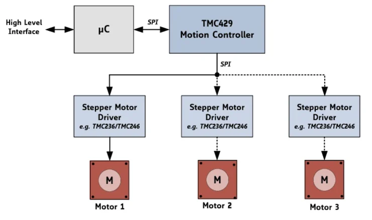
Industry leaders actively integrate SPI into their motion control solutions. Analog Devices, for instance, offers sophisticated motion controller chips that exemplify SPI’s utility. The TMC429 motion controller chip from Analog Devices features an SPI controller and driver interface. This chip is engineered to function as a three-axis motion controller, precisely managing stepper motor positions. It achieves this by generating step and direction pulses, which are then transmitted to external stepper motor drivers. These driver chips subsequently convert the digital pulses into the coil currents necessary to actuate the stepper motors. A notable architectural feature of the TMC429 is its dual SPI interfaces: one dedicated for communication with a higher-level microcontroller (the system master) and another, often configured for daisy-chaining, to communicate with up to three individual stepper motor drivers. This allows for a hierarchical control structure, where a central microcontroller can manage multiple motion axes through a single motion controller chip, optimizing both communication overhead and physical connections.
Similarly, Toshiba has been at the forefront of developing motor controllers tailored for the burgeoning electrification across various vehicle subsystems. As the number of motors in modern vehicles increases—powering everything from window lifts and seat adjustments to advanced steering and braking systems—the demand for robust, integrated motor control solutions grows. Toshiba’s TB9104FTG gate driver for brushed DC motors in automotive applications serves as a prime example. This gate driver boasts an integrated SPI interface alongside on-board motor control circuits. Furthermore, it incorporates built-in motor current sense amplifier circuitry and an integrated PWM drive circuit. This level of integration simplifies the design process for automotive engineers, reduces the bill of materials (BOM), and enhances the reliability of critical vehicle components. The SPI interface enables the vehicle’s central electronic control unit (ECU) to precisely command the motor, monitor its status, and receive diagnostic feedback, all while minimizing wiring complexity.
Comparing SPI with Other Embedded Protocols
To fully appreciate SPI’s advantages in motion control, it is helpful to contrast it with other commonly used embedded communication protocols:
- I2C (Inter-Integrated Circuit): Developed by Philips (now NXP Semiconductors), I2C is another widely adopted serial protocol. It uses only two wires (SDA for data and SCL for clock) and supports multiple masters and multiple slaves through a unique addressing scheme. However, I2C is typically slower than SPI, operates in half-duplex mode (data cannot be sent and received simultaneously), and requires more complex addressing logic. While excellent for low-speed sensor data or configuration tasks, I2C’s speed limitation makes it less suitable for high-throughput, real-time motion control commands compared to SPI.
- UART (Universal Asynchronous Receiver/Transmitter): UART is an asynchronous serial communication protocol that uses only two wires (TX for transmit and RX for receive). Its simplicity and low pin count are attractive, but it lacks a dedicated clock line, relying on pre-configured baud rates for synchronization. This makes it slower and less robust than synchronous protocols like SPI, especially in noisy environments or when precise timing is critical. UART is best suited for simple, point-to-point data logging or console communication, not for the high-speed, synchronized control typical of motion systems.
- Parallel Bus Systems: Before the widespread adoption of serial protocols, parallel buses were common for inter-IC communication. These systems use multiple data lines (e.g., 8, 16, or 32 lines) to transmit data bits simultaneously, offering very high throughput. However, the sheer number of required pins, increased PCB routing complexity, greater power consumption, and susceptibility to EMI (due to crosstalk between numerous adjacent traces) make parallel buses impractical for most modern compact embedded systems, particularly where cost and space are critical. SPI’s ability to achieve respectable data rates with significantly fewer wires offers a compelling balance.
Broader Impact and Future Implications
The widespread adoption of SPI in motion microcontrollers has profound implications across various industrial and consumer sectors. Its contribution to miniaturization and cost reduction is undeniable. By allowing engineers to design more compact and less complex PCBs, SPI facilitates the creation of smaller, lighter, and more cost-effective products. This is particularly crucial in fields such as:
- Robotics: For the precise control of robotic arms, grippers, and mobile platforms, where space and weight are critical design constraints.
- Industrial Automation: In programmable logic controllers (PLCs), motor drives, and sensor arrays that require reliable, high-speed communication within confined enclosures.
- 3D Printing Systems: Where precise motor control for XYZ axes and extruder mechanisms is paramount for print quality.
- Medical Devices: In compact diagnostic equipment, surgical robots, and prosthetics, demanding both precision and reliability in motion.
- Laboratory Equipment: For automating sample handling, fluid dispensing, and microscopy stages.
- Consumer Electronics: In camera modules, optical image stabilization systems, and haptic feedback devices.
As industries move towards greater automation and the integration of smart, interconnected devices (the Internet of Things – IoT and Industry 4.0), the foundational communication protocols like SPI become even more critical. SPI serves as a robust backbone for connecting the "edge devices"—sensors and actuators—to the local microcontrollers that process data and execute commands in real-time. This real-time capability is essential for closed-loop control systems, ensuring high performance, stability, and safety in dynamic environments.
Looking ahead, while SPI’s core principles remain constant, ongoing innovations in semiconductor manufacturing continue to push its boundaries. Higher clock frequencies, improved noise immunity, and integrated diagnostics are continually being developed. Furthermore, the interplay between SPI and other embedded protocols, often within the same system, will continue to evolve, with engineers strategically selecting the most appropriate protocol for each specific communication link based on speed, distance, pin count, and complexity requirements. The simplicity, speed, and efficiency of SPI ensure its enduring relevance as a cornerstone technology for motion control and embedded systems for the foreseeable future, driving innovation in automation and intelligent device design worldwide.