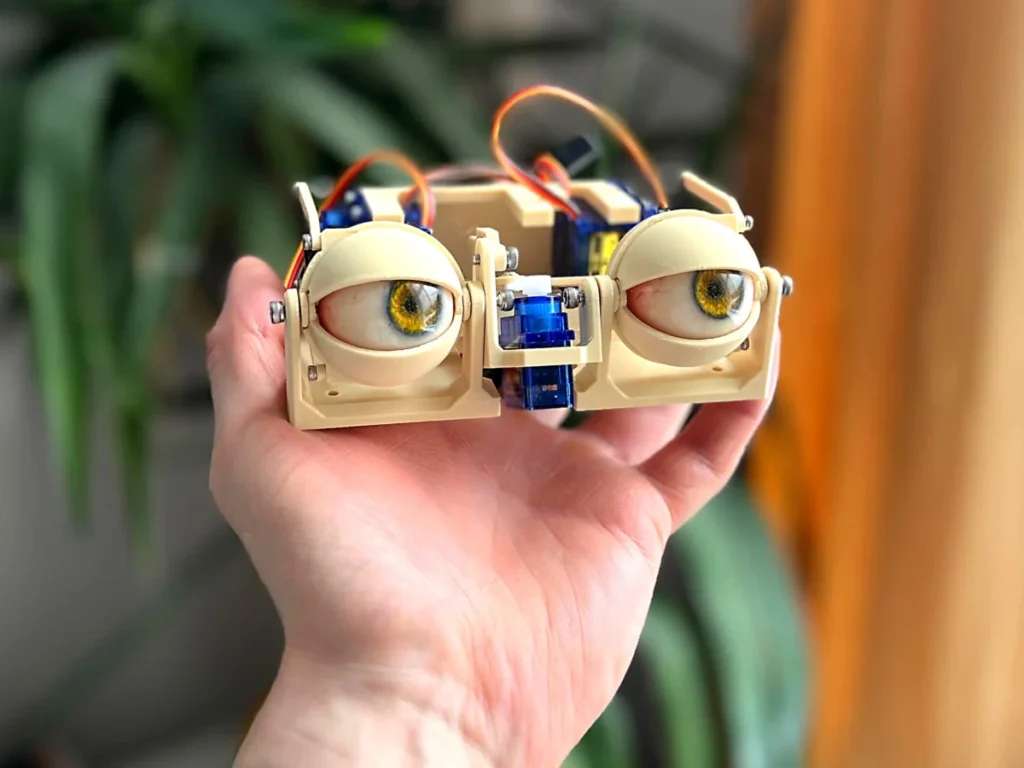
The meticulous construction of animatronic eyes represents a sophisticated fusion of mechanical engineering, precision fastening, and servo control, critical for achieving lifelike realism in robotics and interactive displays. This detailed assembly guide, originating from a burgeoning DIY robotics community, outlines the step-by-step process for building a dual-axis eye motion system complete with articulating eyelids, providing invaluable insights for hobbyists and professionals alike. The project underscores the accessibility of complex animatronic mechanisms through modular design and readily available components, pushing the boundaries of expressive robotic interfaces.

Foundations of Movement: Establishing the Y-Axis Pivot
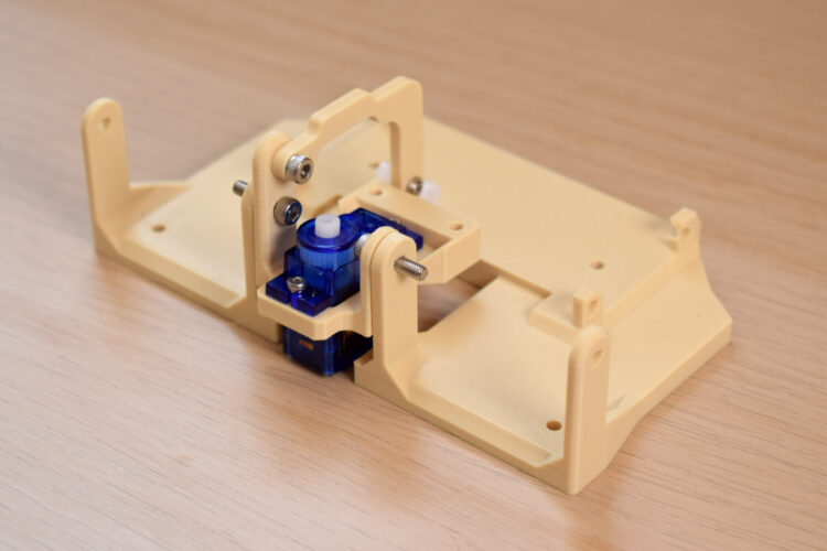
The initial phase of constructing these advanced animatronic eyes focuses on establishing the fundamental pivot point for vertical motion. This involves connecting two primary structural bases, typically fabricated from robust, lightweight materials such as 3D-printed plastics or laser-cut acrylic, using either 10mm or 12mm M3 bolts. The selection of M3 bolts, a standard metric size in small-scale engineering, ensures a secure and durable connection while allowing for precise rotational movement. The specific length (10mm or 12mm) is chosen to accommodate the thickness of the base materials, providing sufficient thread engagement without protruding excessively. This crucial pivot point is engineered to facilitate the y-axis motion of the eye, enabling upward and downward glances, and simultaneously serves as the primary articulation for the eyelids, linking their movement directly to the vertical gaze. The design prioritizes minimal friction at this joint to ensure smooth, responsive motion, a hallmark of convincing animatronic performance. Engineering teams often spend considerable time optimizing such pivot designs, balancing durability with fluidity of movement.
Actuating the X-Axis: Integrating the Primary Servo
Following the establishment of the y-axis pivot, the next critical step is the integration of the primary actuator responsible for horizontal eye movement—the x-axis motion. A compact servo motor, often a model like the TowerPro SG90 due to its widespread availability, cost-effectiveness, and adequate torque for small-scale applications, is strategically positioned within the assembly. These servos are miniature continuous or positional rotation devices, capable of precise angular control, making them ideal for animatronic applications where subtle, controlled movements are paramount. Securing this servo in its designated position requires the use of smaller 4mm or 6mm M2 screws. The M2 size indicates a finer thread and smaller diameter, suitable for securing the servo to its mounting bracket without stripping the delicate plastic housing. Once installed, this servo acts as the dedicated driver for the eye’s horizontal articulation, allowing the animatronic gaze to pan left and right, mimicking the natural saccades and pursuits of biological vision. The integration of this component marks a significant milestone in establishing the dual-axis movement capability of the animatronic eye system.
Crafting the Y-Axis Linkage and Initial Checks
With the main axes defined, attention turns to refining the y-axis movement. This involves attaching the y-axis arm to a sub-base, which acts as an intermediate mounting platform for the various components. A 4mm, 5mm, or 6mm M3 screw is used for this attachment, with the length chosen to provide a firm connection without impeding movement. A servo horn, a plastic or metal lever that attaches to the servo shaft, is then secured to the third hole from its center using a 4mm or 6mm M2 screw. The specific hole chosen on the servo horn is critical; selecting a hole further from the center typically increases the range of motion but decreases torque, while a hole closer to the center provides more torque but a smaller range. The "third hole" suggests an optimized balance for the desired eye movement. Throughout this stage, regular checks are emphasized to ensure the correct orientation of all components. Misalignment at this stage can lead to binding, excessive friction, or incorrect movement kinematics, thereby compromising the realism and longevity of the animatronic mechanism. This iterative process of assembly and verification is standard practice in precision mechanical builds.
Assembling the X-Axis Mechanism: Forks and Adaptors
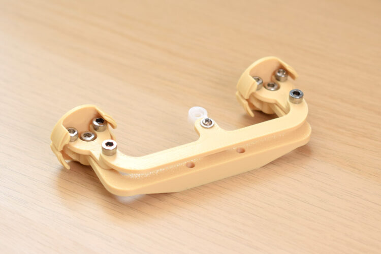
The construction then progresses to the intricate x-axis assembly, which directly manipulates the artificial eyes. This phase begins by screwing the "forks" into the "eye-adaptors" using 4mm, 5mm, or 6mm M3 bolts. The "forks" are components designed to cradle and guide the eye spheres, while the "eye-adaptors" provide the interface between the eyes and the movement mechanism. A key design feature highlighted is that the fork holes are intentionally oversized, allowing the M3 screws to "bite" directly into the material of the adaptor. This self-tapping technique is common in 3D-printed or soft plastic components, creating a strong, customized thread during assembly. Acknowledging potential challenges, the instructions mention that "one goes in on a funny angle but you should be able to get it in," which speaks to the typical minor variances encountered in DIY fabrication and assembly. Such small adjustments are often necessary to compensate for material tolerances or slight misalignments, and experienced makers are adept at navigating these nuances to ensure a functional build.
The Three-Point Connector and Servo Arm Integration
To ensure synchronized and fluid horizontal movement of both eyes, a "three-point connector" is attached to the top of the forks. This component acts as a central linkage, distributing the x-axis servo’s motion evenly to both eye mechanisms. An M3 screw is employed here, again utilizing the principle of biting into an undersized hole in the fork component for a secure, thread-forming fit. Further enhancing the x-axis control, a servo arm is then attached to the final hole at the center of this three-point connector, using a 5mm M3 bolt. The use of the "final hole" implies maximizing the lever arm for the x-axis servo, potentially to achieve a wider range of horizontal movement. A critical note for precision is that the hole on this servo arm may require drilling to a slightly larger diameter, specifically between 2.5mm and 2.8mm, to properly accept the M3 screw. This fine adjustment is essential to prevent binding or stripping the screw. As with previous steps, the instruction to "manipulate the assembly regularly as you build it up, to make sure it all moves OK without friction" underscores the importance of continuous testing and fine-tuning to achieve optimal mechanical performance and prevent wear or jerky movements.
Eye Integration and Center-Link Attachment
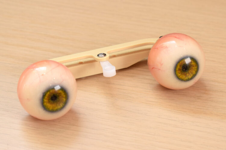
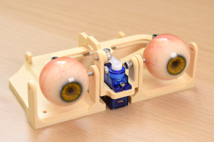
The animatronic eyes themselves are then brought into the assembly. The "eye center-link" is attached to the "eye adaptors" with an 8mm M3 screw. The specific orientation of this center-link is crucial for correct functionality and appearance: the flat surface must face upwards, while the sloping section faces downwards. This precise alignment likely dictates the aesthetic and functional interaction of the eyes with the eyelids or surrounding facial structure. The center-link serves to structurally connect the individual eye units, ensuring they move in a coordinated fashion, a fundamental requirement for conveying a cohesive gaze. At this stage, the actual eye components—typically spheres or domes designed to mimic irises and pupils—can be plugged into their respective adaptors. This step brings the visual aspect of the animatronic design to life, allowing the builder to begin visualizing the final expressive capabilities of the mechanism. The modularity of plugging in the eyes at this stage also allows for easier replacement or customization in the future.
Securing the Core Assembly to the Sub-Base
With the intricate eye movement mechanism now substantially assembled, the entire unit is securely affixed to the central sub-base. This critical fastening step uses two 12mm M3 bolts. The choice of 12mm bolts suggests the need for a strong, deep engagement with the sub-base, ensuring that the entire eye assembly remains rigidly in place despite the dynamic forces exerted by the servos during operation. This secure mounting is paramount for the stability and reliable performance of the animatronic eyes. Any looseness at this central connection point could introduce unwanted wobble or imprecise movements, detracting from the realism of the animatronic’s expressions. The sub-base itself is designed to provide a stable foundation, often incorporating additional mounting points for other components or the larger animatronic head structure. This phase solidifies the mechanical core of the eye system, preparing it for the integration of the control electronics and remaining articulation points.
Powering the System: The Servo Block and TowerPro SG90s
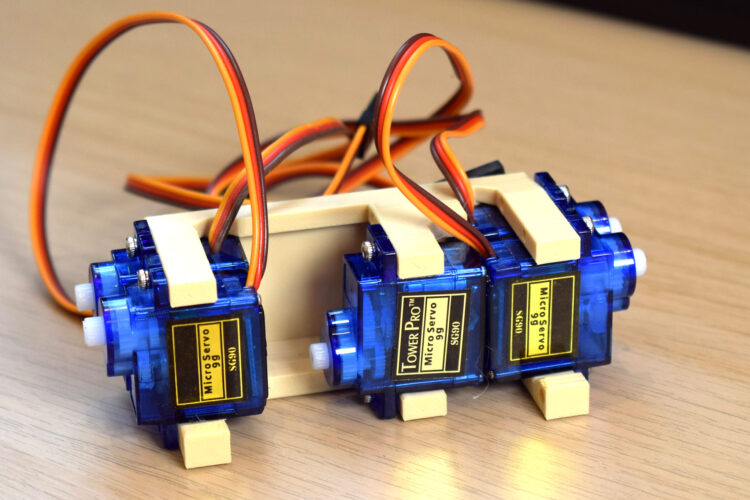
To bring the complex movements of the animatronic eyes and eyelids to life, a dedicated "servo block" is loaded with five TowerPro SG90 servos. The TowerPro SG90 is a widely recognized micro servo in the hobbyist and educational robotics communities, celebrated for its compact size, affordability, and sufficient torque for light-duty applications. The use of five such servos indicates a multi-degree-of-freedom system, beyond just the basic X and Y axis for eye movement. Typically, two servos would control the x-axis, two for the y-axis, and at least two more for the eyelids (one for each, or potentially upper and lower lids separately), bringing the total to six for full independent control. The description of five servos suggests a highly efficient design, possibly with shared servo control for certain movements or a dedicated servo for a specific nuance like brow movement or a primary eyelid.
The correct orientation of each servo within the block is critical, not only for mechanical alignment but also for ensuring proper wiring connections to a control board (e.g., Arduino or Raspberry Pi). Once the servos are precisely positioned, the entire servo block is attached to the main base using four M3x10mm bolts. This robust attachment prevents any shifting or vibration of the servos during operation, which could otherwise translate into jerky or inaccurate eye movements. The modular design of the servo block allows for easy installation, maintenance, and potential future upgrades, embodying the principles of efficient mechanical design in animatronics.
Eyelid Mechanism: Precision Linkages
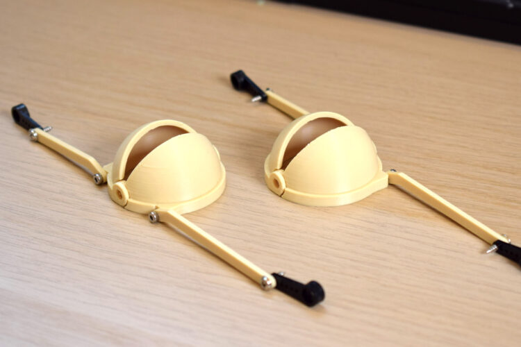
The next stage delves into the intricate mechanics of the eyelids, which are crucial for conveying emotion and adding a layer of biological realism to the animatronic eyes. The builder must carefully identify which eyelid component corresponds to which eye, often guided by photographic references provided in the project documentation. This attention to detail prevents accidental swapping, which could lead to inverted or misaligned eyelid movements. Each relevant eyelid connector is then attached with a 4mm or 6mm M2 screw, chosen for its smaller size and precision, ideal for the lighter forces and more delicate movements of the eyelids.
Subsequently, a servo arm is attached to the other end of the eyelid connector, specifically utilizing the last hole in the servo horn. Similar to previous steps, the selection of the outermost hole on the servo horn is a deliberate engineering choice, designed to maximize the range of motion for the eyelids, allowing them to open and close fully. Given the fine tolerances often required for natural eyelid movement, the servo horn hole may need to be carefully drilled to an even smaller diameter, between 1.5mm and 1.8mm, to ensure a perfect fit for the M2 screw and eliminate any play that could result in imprecise or wobbly eyelid motion. This fine-tuning exemplifies the micro-engineering required to achieve compelling animatronic expressions, where even a fraction of a millimeter can significantly impact the visual outcome.
Final Eyelid Attachment and System Overview
The penultimate step in the mechanical assembly involves attaching the eyelid mechanisms to the main base structure. Crucially, at this stage, the eyelids are secured to their pivot points on the base, but the connection to the servo horns is deliberately deferred. This staged approach is a common and intelligent practice in animatronics and robotics assembly. It allows the builder to first confirm the free and unhindered movement of the eyelids along their intended paths without the influence or resistance of the servos. Once the mechanical linkages are verified to be smooth and frictionless, the servos can be powered up and set to a neutral or "zero" position. Only then are the servo horns connected to the eyelid linkages, ensuring that the initial resting position of the eyelids is correctly calibrated relative to the servo’s starting angle. This method prevents potential damage to the servos or linkages due to misaligned initial connections and ensures that the full range of motion can be properly programmed and utilized.
The complete assembly, as depicted in the provided imagery, showcases a compact yet highly capable animatronic eye system. The modular design, combining custom 3D-printed components with off-the-shelf micro servos and standard fasteners, highlights the significant advancements in accessible robotics. Projects like this are not only valuable for hobbyists and educational institutions but also serve as foundational learning tools for aspiring engineers and designers. They offer a tangible understanding of kinematics, mechanical advantage, and the intricate relationship between physical design and software control—principles that scale up to the complex animatronics found in theme parks, film productions, and advanced humanoid robots. The ability to craft such detailed and expressive mechanisms at a DIY level signals a growing democratization of robotics, empowering a new generation of innovators to explore the frontiers of human-robot interaction and realistic character animation.