The intricate world of modern motion systems relies heavily on robust and efficient communication protocols to orchestrate the precise movements of machinery, robotics, and automated equipment. While high-level network protocols such as Ethernet, EtherCAT, and CAN are indispensable for connecting disparate drives, motors, and controllers across a broader system architecture, a different set of communication standards takes precedence at the micro-level—specifically, within the confines of a controller’s circuit board or directly between integrated circuits (ICs). Among these, the Serial Peripheral Interface, or SPI, stands out as a fundamental and widely adopted standard for synchronous serial data transmission, particularly within embedded systems where space, speed, and reliability are paramount.
Understanding the Serial Peripheral Interface (SPI)
SPI is a master-follower (often referred to as master-slave) communication protocol developed by Motorola in the mid-1980s. Its primary purpose is to facilitate short-distance, high-speed data exchange between a microcontroller (the master) and one or more peripheral devices (the followers). Unlike asynchronous protocols, SPI is synchronous, meaning that a shared clock signal orchestrates the data transfer, ensuring that both the master and follower are perfectly synchronized during communication. This characteristic eliminates the need for complex timing mechanisms or start/stop bits, simplifying hardware and software implementation.
Technical Foundations: How SPI Works
At its core, SPI is a four-wire serial interface supporting full-duplex communication, which means data can be sent and received simultaneously. The four standard signal lines are:
- SCLK (Serial Clock): Generated by the master, this signal synchronizes the data transfer between the master and the follower(s). Data bits are typically shifted in or out on the rising or falling edge of this clock.
- MOSI (Master Out, Follower In): This is the data line from the master to the follower. Data transmitted by the master is received by the follower on this line.
- MISO (Master In, Follower Out): This is the data line from the follower to the master. Data transmitted by the follower is received by the master on this line.
- SS (Slave Select) / CS (Chip Select): Generated by the master, this active-low signal is used to select a specific follower device when multiple followers are connected to the same SPI bus. When a follower’s SS line is low, it is active and ready to communicate; when high, it ignores the SPI bus signals.
Data rates for SPI can vary significantly, ranging from a few megahertz (MHz) up to 10 MHz or even higher in specialized implementations, making it suitable for applications requiring rapid data exchange. The data transmission width is also programmable, typically from 8 to 16 bits, but can extend from 2 to 24 bits depending on the microcontroller and peripheral capabilities. This flexibility allows for efficient transfer of various data types, from simple command bytes to complex sensor readings.
Key Advantages and Considerations
SPI offers several compelling advantages that contribute to its widespread adoption in embedded systems:
- Simplicity: The protocol is relatively straightforward to implement in both hardware and software, requiring minimal overhead.
- High Speed: Synchronous operation allows for fast data rates, often higher than other serial protocols like I2C or UART.
- Full Duplex: Simultaneous sending and receiving of data maximizes throughput.
- No Arbitration: Unlike multi-master protocols, SPI is single-master, eliminating bus arbitration issues.
- Low Power Consumption: Simpler circuitry often leads to lower power requirements.
- Minimal Pins (compared to Parallel): While using four wires, it significantly reduces the pin count and printed circuit board (PCB) space compared to parallel bus systems that might require 8, 16, or more data lines plus control signals. This is particularly critical in miniaturized embedded systems.
However, SPI also has its limitations:
- More Pins than I2C: It uses more wires than I2C (which typically uses two wires: SDA and SCL).
- No Addressing: Without an inherent addressing scheme, each follower requires a dedicated SS line, limiting the number of followers or requiring more GPIO pins on the master. Daisy-chaining can mitigate this but adds complexity.
- No Acknowledgment: SPI does not have a built-in acknowledgment mechanism, meaning the master doesn’t automatically know if the follower successfully received the data. Error checking must be implemented at a higher software layer.
- Single Master: It’s inherently a single-master protocol, making multi-master configurations difficult or impossible without external arbitration logic.
SPI in Context: A Comparison with Other Protocols
To fully appreciate SPI’s niche, it’s useful to briefly compare it with two other prevalent embedded communication protocols:
- I2C (Inter-Integrated Circuit): Developed by Philips (now NXP), I2C uses only two wires (SDA for data, SCL for clock) and supports multiple masters and followers. Each follower has a unique 7-bit or 10-bit address, allowing the master to select a device without dedicated select lines. However, I2C is typically slower than SPI and is half-duplex (data flows in one direction at a time). It also requires pull-up resistors on its lines. SPI is preferred for higher speed, full-duplex communication with fewer devices.
- UART (Universal Asynchronous Receiver/Transmitter): UART is an asynchronous serial protocol requiring only two wires (TX for transmit, RX for receive). It doesn’t use a shared clock; instead, both devices must agree on a common baud rate. This makes it simpler in terms of wiring but less reliable at very high speeds and more susceptible to clock drift. It’s often used for debugging, console communication, or connecting to modules like GPS or Bluetooth. SPI’s synchronous nature and higher speeds make it better suited for direct IC-to-IC communication where precise timing and high throughput are crucial.
The Pivotal Role of SPI in Motion Microcontrollers
In motion control systems, microcontrollers are the brains, executing algorithms to command motors and interpret feedback from sensors. SPI serves as a critical conduit for communication between these microcontrollers and a diverse array of peripheral devices essential for precise motion.
Interfacing with Sensors and Feedback Systems
Motion control relies heavily on accurate feedback. SPI is extensively used to connect various types of sensors to the microcontroller:
- Encoders: High-resolution optical or magnetic encoders provide feedback on motor position, speed, and direction. Many modern absolute and incremental encoders communicate via SPI, offering precise digital readings.
- Accelerometers and Gyroscopes: In applications like robotics, drones, or platform stabilization, inertial measurement units (IMUs) integrate accelerometers and gyroscopes, often communicating their orientation and motion data via SPI to the microcontroller for real-time adjustments.
- Current Sensors: For motor current monitoring, specialized current sense amplifiers or ADCs (Analog-to-Digital Converters) often feature an SPI interface to relay precise current values back to the microcontroller, enabling overcurrent protection, current-mode control, and motor diagnostics.
- Temperature Sensors: Monitoring motor or driver temperature is crucial for preventing overheating and ensuring longevity. Digital temperature sensors frequently use SPI to report readings.
By providing a fast and reliable link, SPI ensures that the microcontroller receives timely and accurate data from these feedback devices, which is vital for closed-loop control, stability, and safety.
Driving Actuators and Motor Control
Beyond sensors, SPI is instrumental in controlling actuators, particularly motor drivers. A common setup involves a microcontroller sending control signals, such as Pulse Width Modulation (PWM) signals, to a motor driver. Many advanced motor drivers now feature integrated SPI ports, allowing the microcontroller to configure various driver parameters, set motor currents, enable/disable outputs, and even select operating modes. In some highly integrated systems, the controller logic and motor driver may reside on the same chip, with internal SPI-like interfaces facilitating communication. This integration reduces component count and simplifies design.
Memory and Display Integration
SPI also facilitates interaction with memory devices and displays:
- Non-Volatile Memory: For storing configuration parameters, calibration data, or firmware updates, microcontrollers often communicate with external flash memory or EEPROMs via SPI. This allows for persistent storage that retains data even when power is removed.
- Small Displays: In embedded systems with user interfaces, small LCD or OLED displays are frequently driven by SPI, allowing the microcontroller to quickly update textual or graphical information.
Diagnostic Capabilities and System Health Monitoring
A significant application of SPI in motion control is for diagnostic purposes. Modern motor drivers and integrated motion control chips are equipped with extensive diagnostic features. Through SPI, the microcontroller can query these devices to retrieve status registers, fault flags (e.g., overtemperature, overcurrent, undervoltage), motor current values, and other operational data. This real-time diagnostic feedback is invaluable for:
- Preventive Maintenance: Identifying potential issues before they lead to catastrophic failure.
- Troubleshooting: Pinpointing the root cause of system malfunctions quickly.
- Performance Optimization: Monitoring operational parameters to fine-tune control algorithms.
- Safety: Implementing safety shutdowns or alerts based on detected anomalies.
Master-Follower Architectures and Scalability
SPI inherently operates in a master-follower configuration. A single master controller can communicate with one or more follower devices. There are two primary ways to manage multiple followers:
- Independent Follower Select: Each follower device is connected to a unique SS (Chip Select) line from the master. To communicate with a specific follower, the master pulls that follower’s SS line low while keeping all other SS lines high. This configuration is straightforward but consumes one GPIO pin on the master for each follower.
- Daisy-Chaining: In this setup, multiple followers are connected in series. The MOSI of the master connects to the first follower’s input, the output of the first follower connects to the input of the second, and so on. A single SS line from the master can select all followers simultaneously. Data is then shifted through the chain. This method saves GPIO pins on the master but requires followers to support daisy-chaining and can be slower as data propagates through all devices. It’s often used for LEDs, shift registers, or certain types of sensors where the order of data is well-defined.
In motion control, both configurations are common. For instance, a microcontroller might use independent SS lines to control several distinct motor drivers, while a daisy-chained setup might be used for a series of position sensors or diagnostic chips that share common data.
Real-World Implementations: Case Studies
The practical application of SPI in motion control is best illustrated through specific examples from leading semiconductor manufacturers.
The Analog Devices TMC429 Motion Controller
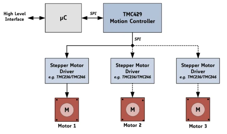
Consider the Analog Devices (formerly Trinamic Motion Control) TMC429 motion controller chip. This specialized IC exemplifies the power of SPI in dedicated motion control. The TMC429 functions as a sophisticated three-axis motion controller, capable of generating precise step and direction signals for stepper motor drivers. It features two separate four-wire SPI interfaces:
- One SPI interface allows a higher-level microcontroller (e.g., a general-purpose MCU like an ARM Cortex-M series) to configure the TMC429, send target positions, read status, and manage its operations. This effectively offloads complex motion profile generation from the main MCU.
- The second SPI interface is dedicated to communicating with up to three daisy-chained stepper motor drivers. The TMC429 sends control parameters and commands to these drivers via SPI, which then convert the step/direction signals into the appropriate coil currents to drive the stepper motors.
This architecture demonstrates how SPI enables a hierarchical control structure, where a dedicated motion controller manages the low-level motor control, freeing the main microcontroller for higher-level tasks like path planning, user interface management, or network communication. The compact nature of SPI also allows for the integration of such powerful chips into space-constrained designs.
Automotive Applications: Toshiba’s TB9104FTG Gate Driver
The automotive industry is undergoing a significant transformation with increasing electrification, leading to a proliferation of motors within vehicles—for power windows, seat adjusters, mirrors, HVAC flaps, electronic power steering, and more. This trend demands robust, efficient, and compact motor control solutions. Toshiba’s TB9104FTG gate driver is a prime example of an automotive-grade motor controller leveraging SPI.
Designed for brushed DC motors, the TB9104FTG integrates several critical components:
- SPI Interface: This allows the vehicle’s central electronic control unit (ECU) or a local microcontroller to configure the gate driver, set operational modes, and retrieve diagnostic information. This integration simplifies wiring and reduces the number of control signals needed.
- On-board Motor Control Circuits: The chip incorporates the necessary logic to drive the motor, often including H-bridge control.
- Built-in Motor Current Sense Amplifiers: These circuits precisely measure the motor current, enabling closed-loop current control, stall detection, and overcurrent protection, all reported via SPI.
- Built-in PWM Drive Circuit: The chip can directly generate the PWM signals required to control motor speed and torque, reducing the processing load on the external microcontroller.
The use of integrated SPI in such automotive components highlights its importance in achieving functional safety (e.g., reporting faults instantly), reducing system complexity, and enabling advanced features in increasingly sophisticated vehicle subsystems.
Broader Industry Adoption
Beyond these specific examples, numerous other semiconductor manufacturers like STMicroelectronics, NXP, Microchip, and Texas Instruments extensively integrate SPI support into their microcontrollers, digital signal controllers (DSCs), and various peripheral ICs. This widespread adoption underscores SPI’s role as a de facto standard for embedded communication, enabling engineers to select from a broad ecosystem of compatible components for their motion control designs in fields such as:
- Industrial Automation: Robotics, CNC machines, conveyor systems, automated test equipment.
- 3D Printing: Precise stepper motor control for extruder and gantry movements.
- Medical Devices: Infusion pumps, diagnostic equipment, surgical robots requiring fine motor control.
- Consumer Electronics: Camera gimbals, optical image stabilization, small appliance motors.
Advanced Operational Aspects: SPI Modes
A crucial detail in SPI communication is the concept of SPI modes, defined by two parameters: Clock Polarity (CPOL) and Clock Phase (CPHA). These parameters determine when data bits are sampled and when the clock signal idles (rests). There are four common SPI modes:
- Mode 0 (CPOL=0, CPHA=0): Clock idles low. Data is sampled on the rising edge of the clock.
- Mode 1 (CPOL=0, CPHA=1): Clock idles low. Data is sampled on the falling edge of the clock.
- Mode 2 (CPOL=1, CPHA=0): Clock idles high. Data is sampled on the falling edge of the clock.
- Mode 3 (CPOL=1, CPHA=1): Clock idles high. Data is sampled on the rising edge of the clock.
Both the master and the follower must be configured to the same SPI mode for successful communication. This flexibility allows SPI to adapt to various peripheral ICs that may have different timing requirements.
The Broader Impact and Future Outlook of SPI in Motion Control
The enduring relevance of SPI in motion microcontrollers has far-reaching implications for the design and capabilities of modern automated systems.
Driving Miniaturization and Integration
SPI’s efficient use of PCB space, stemming from its serial nature and minimal wire count compared to parallel buses, is a key enabler for miniaturization. As demand for smaller, more compact, and increasingly portable motion systems grows (e.g., in medical wearables, micro-robotics, or compact industrial actuators), SPI’s ability to facilitate robust communication within tight physical constraints becomes invaluable. Furthermore, the trend of integrating SPI controllers directly into microcontrollers and system-on-chips (SoCs) simplifies hardware design, reduces external component count, and lowers manufacturing costs.
Enhancing Precision and Efficiency
The high data rates and full-duplex capabilities of SPI contribute directly to the precision and efficiency of motion control. Faster feedback loops from sensors to the microcontroller mean quicker response times and more accurate adjustments, leading to smoother, more precise movements. The ability to simultaneously send commands and receive status information maximizes throughput, allowing complex control algorithms to operate with minimal latency. This is particularly critical in applications requiring real-time performance, such as high-speed pick-and-place robotics or finely tuned scientific instruments.
Future Trajectories
As motion control systems become more sophisticated, demanding even higher levels of integration, lower power consumption, and enhanced data security, SPI is expected to evolve. While the core protocol remains stable, advancements will likely focus on:
- Higher Clock Frequencies: Pushing data rates further to support more data-intensive applications.
- Enhanced Error Checking: While not inherently part of SPI, higher-level software protocols built atop SPI may incorporate more robust error detection and correction.
- Standardized Security Layers: Integrating security features at the hardware or firmware level to protect data transmitted over SPI, crucial for IoT and connected industrial systems.
- Specialized SPI Variants: The emergence of specialized derivatives or extensions to address specific industry needs, much like how Quad-SPI (QSPI) has extended performance for flash memory.
Conclusion
The Serial Peripheral Interface (SPI) is more than just another communication protocol; it is a foundational technology underpinning the sophisticated control mechanisms of modern motion systems. Its synchronous, full-duplex, four-wire architecture offers a compelling balance of speed, simplicity, and efficiency, making it the preferred choice for chip-level communication within embedded motion microcontrollers. From integrating precision sensors and driving complex motor controllers to facilitating vital diagnostics and enabling compact designs, SPI plays a pivotal role. As industries continue to advance towards more automated, precise, and miniaturized solutions, the importance of robust and efficient communication protocols like SPI will only grow, cementing its status as an indispensable component in the ongoing evolution of motion control technology.