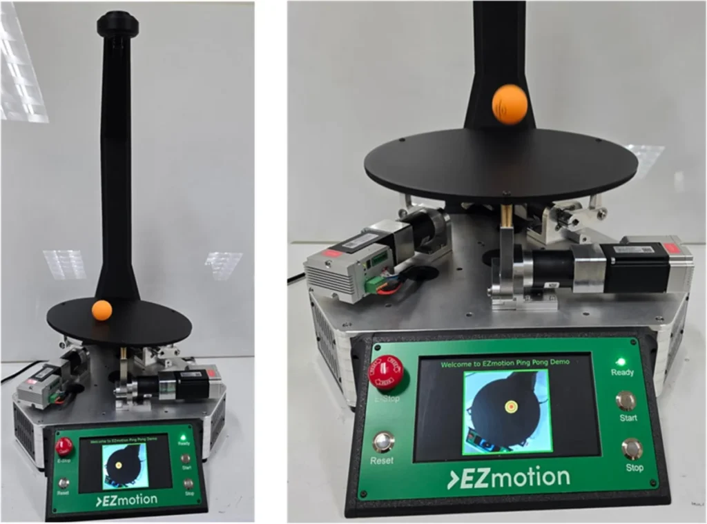
A cutting-edge demonstration of advanced motion control technology has recently unveiled a parallel-kinematics platform capable of manipulating a ping-pong ball with unprecedented real-time precision. This sophisticated system, powered by a specialized line of servomotors, integrates synchronized servo actuation, visual feedback, and real-time kinematic computation to achieve dynamic balancing, swirling, and bouncing of the lightweight object. The innovative setup not only showcases the high performance of these servomotors but also highlights solutions to critical engineering challenges such as visual-feedback latency, multi-axis synchronization, and the execution of real-time inverse kinematics and Proportional-Integral-Derivative (PID) control on embedded hardware.
The core of this achievement lies in a newly developed three-axis parallel platform, meticulously engineered to exhibit the dynamic capabilities of integrated servomotors. These motors, which feature onboard drivers, angle sensors, and CANopen support, deliver high-resolution motion, immediate response, and tightly coordinated multi-axis synchronization. The choice of a ping-pong ball as the controlled object is particularly insightful; its minimal mass and high sensitivity to external forces make it an ideal, albeit challenging, subject to demonstrate the system’s ability to manage complex, unpredictable movements in a dynamic environment. This level of precision and responsiveness is not merely an impressive feat of engineering but a tangible proof-of-concept for real-world applications across diverse industries.

The Technological Backbone: Integrated Servomotors and Control Architecture
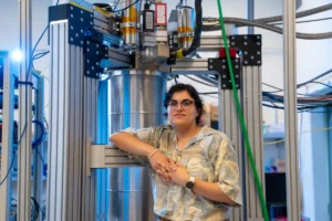
At the heart of the platform’s exceptional performance are integrated servomotors, specifically the MMS740100-24-R2-1 (or MMS740100-24-C2-1 model, a fully integrated 40-mm smart motor from EZmotion, developed with contributions from Monolithic Power Systems’ mechatronics engineer, Charan Bhamra). These advanced units are designed to simplify complex motion control systems by integrating a permanent-magnet synchronous motor with its driver module, angle sensors, and a motion controller into a single, compact package. This integration dramatically reduces the need for external boards and extensive wiring, offering a plug-and-play solution that enhances reliability and streamlines system architecture.
Each servomotor acts as a self-contained control node, boasting an embedded motion controller that runs a nested control loop. This sophisticated loop efficiently regulates current, velocity, and position in real-time, ensuring optimal power delivery to the motor windings and precise execution of motion commands. A 14-bit resolution magnetic position sensor tracks the shaft’s position with sub-degree accuracy, providing the critical feedback necessary for high-precision control. Furthermore, the onboard CAN transceiver facilitates direct integration into a CANopen network, a standardized communication protocol widely used in automation for robust, real-time data exchange. A dedicated power management solution ensures stable internal voltages, safeguarding operations.

A Dual-Processor Approach: Perception and Control
The system’s architecture employs a clever division of computational labor between two distinct processing units to optimize both real-time responsiveness and sophisticated visual analysis.
-
Visual Feedback and Image Processing (Raspberry Pi 5): A top-mounted USB camera captures video frames at a moderate yet effective rate of 40 frames per second. This visual data is then channeled to a Raspberry Pi 5 device, which acts as the system’s perception hub. Running a lightweight Python script with OpenCV, the Raspberry Pi performs real-time image processing. To accurately track the ping-pong ball, Gaussian blur is applied to the frames to reduce noise, followed by a conversion to the Hue, Saturation, Value (HSV) color space, which is more robust for color-based object detection than RGB. The ball, sporting an orange color mask, is then identified through contour filtering, which helps delineate its boundaries. Its center coordinates (X and Y position) are extracted from the smallest circle enclosing the largest contours, providing precise planar location. Crucially, the ball’s Z-position (height) is inferred from its apparent diameter in pixel units; as the ball approaches the camera, its detected diameter increases, allowing for a real-world Z-position translation in millimeters. The Raspberry Pi also connects to a local display via HDMI, providing a live feed of the camera with superimposed ball-tracking information for monitoring and debugging. The processed position and height data of the ball are then sent to the Cortex M4 microcontroller unit (MCU) via a Serial Peripheral Interface (SPI) communication link, a high-speed, short-distance serial communication protocol.

-
Real-time Control and Kinematic Computation (Cortex M4 MCU): The Cortex M4 microcontroller unit serves as the motors’ initiator controller and the platform’s real-time decision-maker. It is responsible for the core control loop and the complex kinematic model of the parallel platform. The central control algorithm is built around a PID (Proportional-Integral-Derivative) controller, which is a widely used feedback control loop mechanism. This PID algorithm continuously calculates the necessary platform tilt angle to minimize the positional error of the ping-pong ball.
The MCU’s role is critical in translating abstract control commands into concrete motor actions. First, the kinematic model takes the calculated platform tilt-angle information and translates it into specific position targets for each of the three servomotors. This is the inverse kinematics problem: determining the joint angles required to achieve a desired end-effector (platform) pose. Once these targets are computed, the motors enter Cyclic Synchronous Position (CSP) mode via CANopen. In CSP mode, the MCU sends precise position setpoints to each motor at a fixed, deterministic update rate. This ensures highly synchronized and deterministic motion across all three axes, allowing the platform to stabilize rapidly and precisely respond to fast-changing inputs, a paramount requirement for controlling a highly dynamic object like a ping-pong ball.
Kinematic Model Calculations: The Mathematics of Motion

Understanding the platform’s movement relies heavily on its kinematic model, which defines how the system’s geometry translates motor inputs into platform motion and vice-versa. The MCU utilizes an inverse kinematic approach to compute the necessary motor crank angles to achieve a target platform tilt angle and Z translation.
The process begins by defining the global positions of the fixed-base joints and the local positions of the moving platform joints, which are distributed on a circle of a given radius (referred to as Equation 1 in the original source). Rotation matrices are fundamental to defining how the platform moves in 3D space. These matrices describe rotations around the X, Y, and Z axes by respective angles (θx, θy, θz), as represented by Equations 2, 3, and 4. The combined rotation matrix (Equation 5) then describes the overall orientation of the platform’s axes relative to the base’s axes.
With the combined rotation matrix, the actual positions of each platform joint in global coordinates can be determined (Equation 6). Once these global platform joint positions are known, the needed length of each limb connecting the base to the platform can be calculated as the straight-line distance between the base joint and the transformed platform joint (Equation 7). Finally, based on the required length of each limb, the motor crank angle is computed using the known lengths of the crank arm and the connecting rod (Equation 8). These intricate calculations, performed in real-time by the MCU, are essential for precise and coordinated control of the platform’s orientation and translation.

Demonstration Modes: A Test of Agility
The parallel platform operates through a sequence of demonstration modes, each designed to highlight different aspects of the servomotors’ and control system’s capabilities:
-
Balancing Mode: The initial and most fundamental test, where the target ball location is fixed at the exact center of the platform. The PID controller continuously adjusts the platform’s tilt angles (θx and θy) to minimize any positional error, effectively keeping the ball stationary at the platform’s center. This mode demonstrates the system’s stability and ability to counteract disturbances.

-
Circular Swirling Mode: This dynamic mode challenges the system to guide the ball along a predefined circular trajectory with a 100mm radius in the XY plane. The target trajectory is set by a two-dimensional array of time-varying reference points. This showcases the system’s ability to execute precise, continuous, and dynamic motion profiles, demonstrating coordination across all three axes to maintain the ball’s path.
-
Bouncing Mode: Perhaps the most complex and visually engaging mode, it aims to maintain the ball at a target height, centered on the platform. To initiate bouncing, the system first enters an "oscillation phase" where the platform undergoes rapid vertical movement, gradually imparting mechanical energy to the ball. Once a predefined energy threshold is reached—indicating consistent bouncing—the controller transitions to a sustained bouncing mode. In this phase, the controller applies minimal, synchronized vertical motion to maintain the bounce, focusing on optimal energy efficiency rather than driving the ball higher. The ball’s total energy (kinetic and potential) and velocity (computed from height differences over time) are estimated to inform the control loop, highlighting the system’s ability to manage kinetic states.
Synchronized Motion with CANopen Cyclic Synchronous Position (CSP) Mode

The use of CANopen’s Cyclic Synchronous Position (CSP) mode is pivotal for achieving the high degree of synchronization required by the parallel platform. CANopen, a communication protocol based on the Controller Area Network (CAN), is robust and widely adopted in industrial automation. While other CANopen modes, such as Cyclic Synchronous Velocity (CSV) and Cyclic Synchronous Torque (CST), are tailored for velocity and torque-driven applications, CSP mode is specifically designed for deterministic, position-based multi-axis control.
In CSP mode, the MCU, acting as the initiator, broadcasts precise position setpoints to each servomotor at a fixed and deterministic update rate. Each motor, in turn, performs internal linear interpolation between consecutive setpoints to ensure a smooth and continuous trajectory, even though the position targets are sampled discretely. This means the motor controllers do not generate their own trajectories but rather meticulously follow the targets fed by the central MCU. From a communication standpoint, CSP mode relies on Process Data Object (PDO) messages containing these absolute target positions. These PDOs can be mapped, configured, and stored in the motor’s non-volatile memory, guaranteeing that the motor shaft follows a seamless path. This highly coordinated and jitter-free motion across all three limbs is essential for the platform’s precise control over the ping-pong ball.
A Refined Sequence of Operation

The platform’s operational sequence is carefully orchestrated for reliability and user interaction. It begins with a torque-based homing routine for all servomotors. During this critical initialization phase, each limb retracts inward at a controlled speed until it physically encounters its mechanical hard stop. This process establishes a repeatable and accurate zero position for all axes. Upon successful homing, the platform automatically ascends to a predefined mid-height along the Z-axis, signaling readiness with a green status LED. At this point, a user can place the ping-pong ball on the platform.
Once initialized, the manipulator enters its active demonstration sequence, starting with the balancing mode. This is followed by a 30-second period of circular swirling, and then 30 seconds of bouncing. This sequence continuously loops, providing an ongoing demonstration of the system’s dynamic capabilities. Throughout the entire process, a 7-inch display provides real-time visual feedback, showcasing the ball’s motion and the system’s responsive control.
Broader Implications and Real-World Impact

The capabilities demonstrated by this parallel-kinematics platform extend far beyond a mere ping-pong ball game. The system’s ability to deliver real-time response, tight multi-axis synchronization, and high-resolution motion control on embedded hardware holds significant implications for a wide array of industrial and medical applications.
-
Medical Robotics: Architectures similar to this demonstration are critical in medical robotics, where precision and stability are paramount. Applications include stabilizing endoscopic instruments during minimally invasive surgeries, guiding delicate surgical tools, and assisting in micro-procedures where sub-millimeter accuracy and jitter-free motion are essential for patient safety and surgical efficacy. The integrated nature of the servomotors simplifies the design of compact, sterile robotic arms.
-
Industrial Automation: In manufacturing and industrial automation, integrated servomotors find application in high-precision tasks. They can impart motion to optical alignment stages for precise component positioning, power pick-and-place heads in assembly lines for rapid and accurate part handling, and drive micro-assembly manipulators for fabricating intricate components. The simplified wiring and compact footprint of integrated motors are particularly beneficial in dense industrial environments where space is at a premium and reliability is crucial.

-
Delta Robots and 3D Printers: Delta 3D printers and high-speed delta pick-and-place machines frequently utilize parallel kinematic structures due to their inherent advantages in speed, rigidity, and payload capacity relative to their mass. Servo-driven delta robots benefit immensely from the real-time, synchronized control demonstrated here, enabling faster print speeds, higher throughput in packaging, and greater accuracy in material handling.
According to Charan Bhamra, Mechatronics Engineer at Monolithic Power Systems, whose components contribute to the servomotors’ advanced functionality, "This demonstration platform effectively showcases the synergy between powerful integrated motor technology and intelligent real-time control. The challenges of precisely manipulating a highly dynamic object like a ping-pong ball underscore the robust performance and seamless integration of our solutions, which are critical for driving the next generation of automation and robotic systems."
A spokesperson for EZmotion, the developer of the MMS740100-24-C2-1 integrated smart motor, further commented, "Our aim is to simplify complex motion control while maximizing performance. By integrating all essential components – from the sensor and driver to the controller and communication interface – into a single device, we empower engineers to develop more agile, efficient, and reliable robotic systems. This parallel platform is a testament to the versatility and precision our integrated servomotors bring to the table, opening doors for innovation in fields demanding the highest levels of accuracy and responsiveness."

The global market for servomotors and drives continues to expand, driven by the relentless march of industrial automation, the proliferation of robotics, and the increasing demand for precision manufacturing in sectors ranging from automotive to electronics. Reports indicate a steady growth trajectory, with a focus on smart, integrated solutions that offer enhanced connectivity, energy efficiency, and ease of deployment. This demonstration by EZmotion, featuring the advanced capabilities of integrated servomotors, aligns perfectly with these market trends, signaling a future where complex robotic tasks become more accessible and efficient to implement. The underlying technologies, particularly the sophisticated interplay of real-time vision, kinematics, and synchronized multi-axis control, represent a significant step forward in the evolution of motion control systems.